Partially transparent photovoltaic modules

a photovoltaic module, partially transparent technology, applied in the direction of photovoltaic supports, manufacturing tools, welding/soldering/cutting articles, etc., can solve the problem of cell opaqueness

Inactive Publication Date: 2005-02-22
BP CORP NORTH AMERICA INC
View PDF15 Cites 161 Cited by
  • Summary
  • Abstract
  • Description
  • Claims
  • Application Information

AI Technical Summary

Benefits of technology

We discovered that the photovoltaic cells and modules such as the one described in FIG. 1 can be made partially transparent by scribing the back contact. We also discovered that the back contact can be removed in a specified pattern on the photovoltaic cell or module using a laser, and preferably a computer-controlled laser, such that the cell or module can have a logo or other sign such that when the photovoltaic cell or module is viewed the logo or sign is highly noticeable. The photovoltaic cell or module therefore functions both as a means for generating electric current and as a source of information such as an advertisement or means of identification. We also discovered that if it is desirable to have a photovoltaic module that transmits light without regard to the need to have a logo or other design or information on the photovoltaic cell, a highly efficient means for making such a module comprises scribing with a laser, or otherwise forming lines or interconnecting holes through the back contact and in a direction that crosses the direction of the interconnects of the photovoltaic module. Preferably, such scribe lines are perpendicular or nearly so to the direction of the interconnects. It is also preferable that such scribe lines run completely across the photovoltaic module up to but not crossing the bus bars of the first and last cells of the series of cells in a module. The number of such scribes which are made on the back contact will determine the degree of transparency. Of course, for each scribe, that amount of area of the cell becomes photovoltaically inactive. However, we determined that the scribes made in the manner described above, particularly where the scribe comprises a series of connected holes to form a line, provides for the least amount of loss of photovoltaic activity.

Problems solved by technology

The light is reflected by the rear contact back into the p-i-n junction However, since the back contact generally covers the entire surface of the photovoltaic cell, the cell is opaque when the back contact is made of a metal such as aluminum and does not transmit or allow any light to pass through.

Method used


Image

  • Partially transparent photovoltaic modules
  • Partially transparent photovoltaic modules
  • Partially transparent photovoltaic modules

Examples


example 1

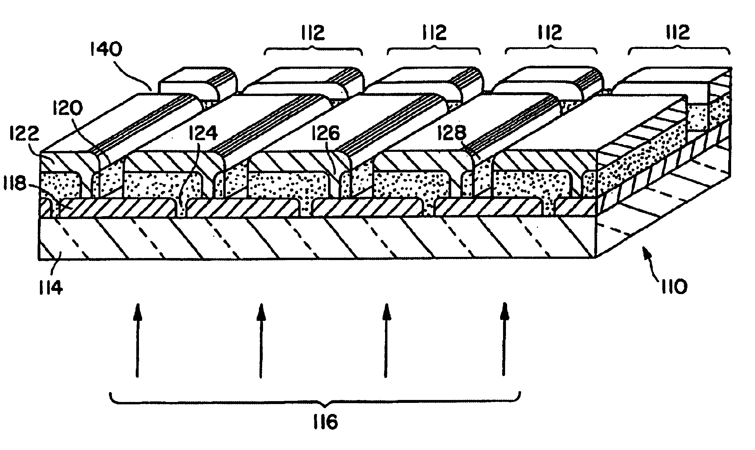
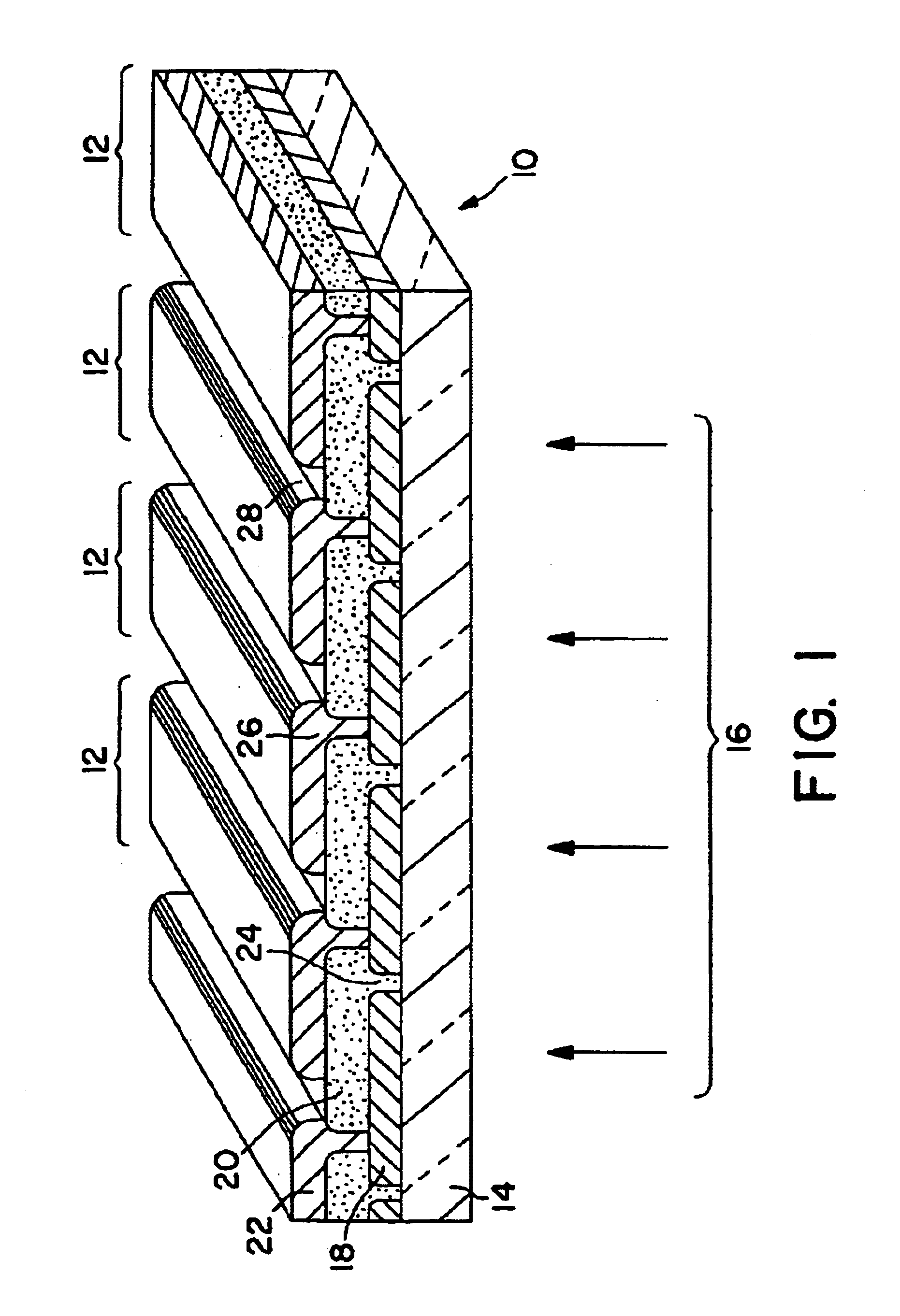
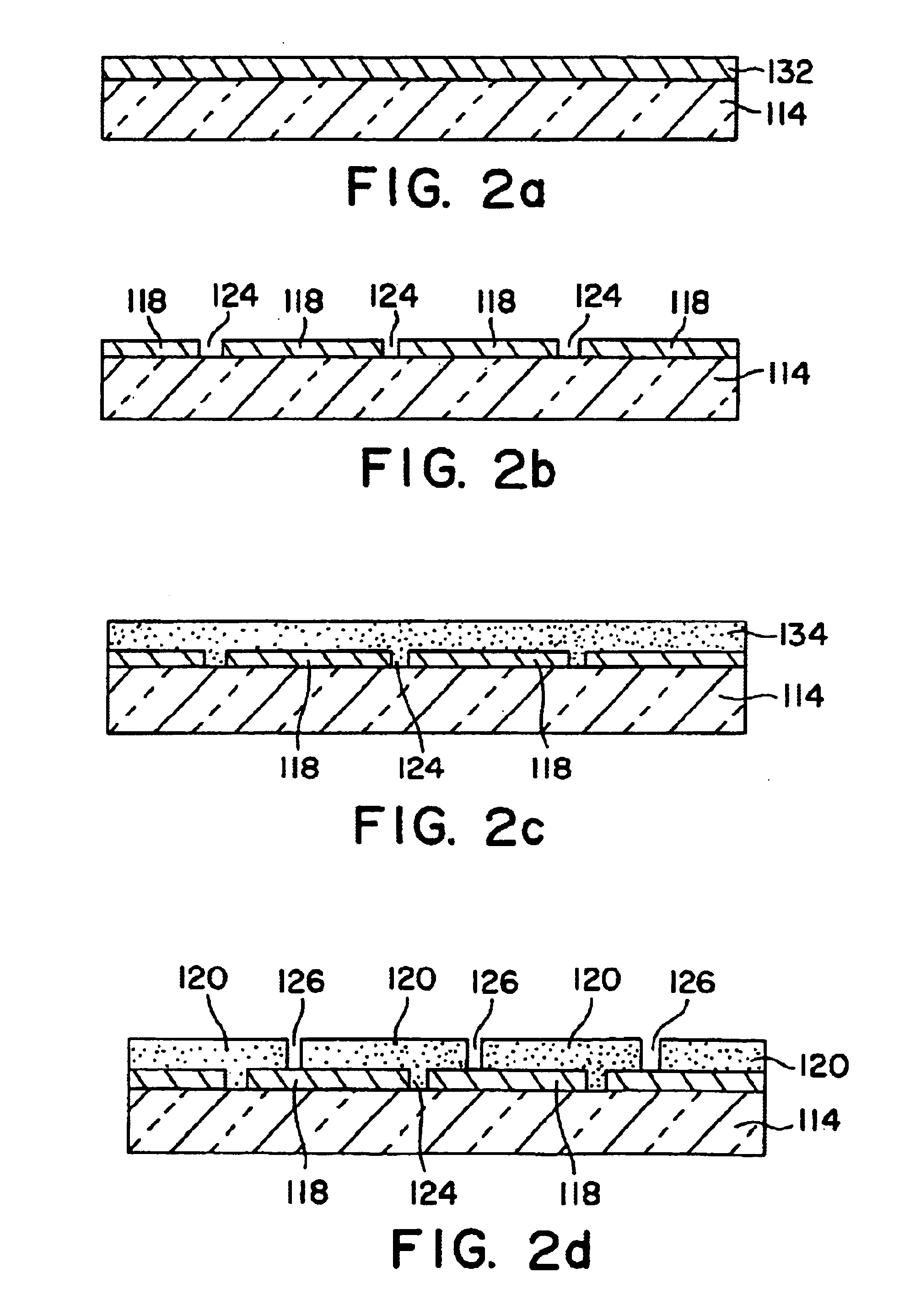
A partially transparent photovoltaic (PV) module with 5% transmission line pattern was made from what was otherwise a thin-film, amorphous silicon BP Solar production PV module (26×48 inches, MV) as follows.

The apparatus used was a high power Nd:YVO4 laser capable of working at 100 kHz and output about 10 W; an XY scanner with mirrors coated for high power laser applications; a laser focusing lens; a beam expander and two mirrors. The XY scanner was a combination of X and Y axis mirrors each controlled by a galvanometer. The focusing lens was mounted on a micrometer that allowed adjustment of the laser focus accurately. The laser beam from the laser was collimated by the beam expander and then directed to the focusing lens by two mirrors. The focused laser beam was projected to the work surface by the XY scanning mirrors. The galvanometers positioned the beam to the desired location on the PV module. The laser beam was directed from the glass substrate side of the module. The microm...

example 2

A partially transparent photovoltaic (PV) module with 10% transmission line pattern was laser prepared as follows.

Same as Example 1, except the scribe line spacing was reduced to about 1 mm.

example 3

A dynamic focusing unit was used to replace the focusing lens in Example 1. The dynamic focusing ensured the laser focused on the working surface at all times during the laser scanning, leading to more uniform coverage across the PV module.


PUM

PropertyMeasurementUnit
widthaaaaaaaaaa
widthaaaaaaaaaa
widthaaaaaaaaaa

Abstract

A photovoltaic cell comprising a supporting substrate, a front contact layer on the substrate, a layer or layers of semiconductor material and a back contact layer comprising a metal, the back contact having areas without metal thereby permitting the passage of light through the cell.

Description

FIELD OF THE INVENTIONThe present invention relates to partially transparent photovoltaic cells and modules and methods for their manufacture. More particularly, the present invention relates to partially transparent amorphous silicon photovoltaic cells and modules wherein the transparency is provided by removing at least part of the back contact layer of the photovoltaic cell. This invention also relates to photovoltaic modules where the removal of the back contact can be used to form a design or logo on the photovoltaic modules so that when viewed from the front or back the design or logo is apparent.A conventional thin film photovoltaic cell typically includes a front contact disposed on a substrate wherein the front contact is made of, for example, a metal oxide such as tin oxide, a p-i-n or PIN junction and a back or rear contact made of, for example, a metal such as aluminum. The p-i-n or PIN junction includes a layer of a semiconductor material doped with a p-type dopant to f...

Claims


Application Information

Patent Timeline
Patent Type & Authority Patents(United States)
IPC IPC(8): H01L21/00H01L21/02H01L21/301H01L21/44H01L31/00B23K26/00B23K101/36H01L27/142H01L31/04H01L31/20
CPCH01L31/046H02S20/00Y02E10/50H01L31/0463H01L31/0468H02S20/10
Inventor OSWALD, ROBERT S.LIU, SHENGZHONG
Owner BP CORP NORTH AMERICA INC
Why Eureka
Try Eureka