Apparatus and method for determining wavelength from coarse and fine measurements

a wavelength and coarse measurement technology, applied in the field ofapparatus and a wavelength determination method of optical signals, can solve the problems of limited wavelength resolution, interference affecting the operation of entire telecommunications networks, and limited performance of prior art wavelength lockers, and achieve the effect of effective visualization of the wavelength of optical signals

Inactive Publication Date: 2005-02-22
PICARRO
View PDF14 Cites 18 Cited by
  • Summary
  • Abstract
  • Description
  • Claims
  • Application Information

AI Technical Summary

Benefits of technology

An objective of the present invention is to provide an apparatus that is able to determine the wavelength of an optical signal, in particular an apparatus that utilizes only two detectors to sample the spatial interference / fringe pattern to provide fine wavelength information and a supplementary filter and associated detector combination to provide coarse wavelength information. In essence, it is an objective of the present invention to provide an apparatus for and an associated methodology to determine the absolute wavelength of an optical signal by determining both a coarse wavelength response and a fine wavelength response, and then combining the two responses to derive the absolute wavelength.
Another objective of the present invention is to integrate the functionality of the coarse wavelength response and the fine wavelength response into a single, easy-to-fabricate and inexpensive device.
These and other advantages of the present invention will become apparent upon reading the following description.
To address the shortcomings of the prior art the present invention provides an apparatus for determining the wavelength of an optical signal from a coarse wavelength response and a fine wavelength response. The coarse wavelength response is obtained by a detection mechanism from an optical filter that has a wavelength-dependent response to the optical signal. The optical filter can be an element whose wavelength-dependent response is electrical or an element whose wavelength-dependent response is optical, such as a varying reflection and / or transmission level. The detection mechanism is any suitable detector or circuit, depending on the type of wavelength-dependent response, i.e., electrical or optical, delivered by the optical filter. For the purpose of obtaining the fine wavelength response the apparatus has an interferometer for receiving the optical signal and generating from it an interference pattern. Two photodetectors are placed in the interference pattern at a quadrature separation from each other, i.e., at locations in the interference pattern that are π / 4 or 90° out of phase. The two photodetectors generate two corresponding intensity signals from which a unit determines the fine wavelength response. The apparatus is also equipped with a processing logic for determining the wavelength from the coarse and fine wavelength responses.
In one embodiment the interferometer is an etalon, preferably a wedge etalon. The optical signal is incident on the etalon from a predetermined angle to obtain the interference pattern between light reflected off or from the front surface and the back surface of the etalon. To obtain a clean interference pattern the apparatus is also equipped with a device such as an aperture for eliminating higher-order reflections from propagating from the interferometer to the two photodetectors.
In another embodiment, the two intensity signals obtained from the two detectors positioned in the interference pattern are plotted in an x-y plane. Meanwhile, the coarse wavelength response is plotted along a z-axis. This 3-dimensional representation of the fine wavelength response and coarse wavelength response traces a corkscrew pattern and enables a particularly effective visualization of the wavelength of the optical signal.

Problems solved by technology

Such shifts in wavelength may result in disturbances affecting the operation of entire telecommunications networks.
These approaches tend to be simple, but they have a limited wavelength resolution.
Unfortunately, the performance of prior art wavelength lockers is usually limited by difficulties encountered in providing high-precision temperature compensation over the operating range of the semiconductor laser without resorting to expensive on-board thermo-electric control.
In wavelength lockers using etalons the temperature affects the optical path length in the etalon, which ultimately translates into wavelength errors for the locked laser.
This design also suffers from the disadvantage that the high precision etalon (oftentimes a multi-element, air-spaced design) is costly, and that one cannot determine on which wavelength channel the laser is running, because wavelength lockers do not measure absolute wavelength.
Unfortunately, these devices are generally too large and costly for applications in telecommunications.
Although Green's teaching resolves a number of the prior art problems, it still requires a complex apparatus, including the oscillating retroreflector or three sensors in the interference pattern to obtain wavelength information.
However, this approach provides only for wavelength locking, since it is not capable of determining absolute wavelength.
The primary disadvantage of these methods and devices is that they cannot be used to easily and cheaply ascertain which particular channel the errors are associated with.

Method used


Image

  • Apparatus and method for determining wavelength from coarse and fine measurements
  • Apparatus and method for determining wavelength from coarse and fine measurements
  • Apparatus and method for determining wavelength from coarse and fine measurements

Examples


example

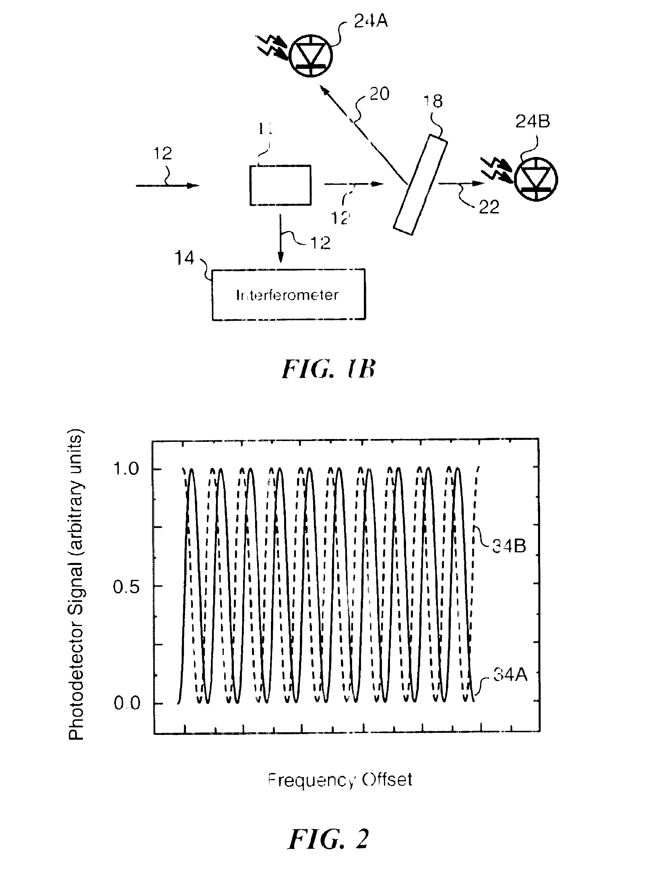
The following example is intended to provide a person skilled in the art with specific parameters to be used in designing an apparatus analogous to the one discussed above in reference to FIG. 5. This example is provided for illustration purposes only and does not impose any limitations on the invention. In this example, sample optical signal 52 propagates through front surface 68 of 400 GHz etalon 62, whose back surface 70 bears a 60% reflective coating 64. Optical signal 52 undergoes refraction, and is reflected off back surface 70 to the front surface 68, and again undergoes refraction as it emerges through front surface 68 in the form of second beam 80. Also, a portion of optical signal 52 is reflected off front surface 68 of etalon 62 in the form of first beam 78.

In essence, etalon 62 splits the optical signal 52 into beams 78, 80 representing two copies of the optical signal 52 with slightly different propagation directions. Etalon 62 is designed such that the desired beam ang...


PUM


Abstract

The present invention provides an apparatus for determining a wavelength of an optical signal by determining a coarse wavelength response and a fine wavelength response. The coarse wavelength response is achieved by utilizing an optical filter. A suitable detector detects the wavelength-dependent response and conveys the determined coarse wavelength response to the processing logic. The fine wavelength response is achieved by utilizing an interferometer that is capable of generating an interference pattern. Two detectors are disposed in the interference pattern at a quadrature separation from each other and detect the intensity responses at their respective locations. The intensity responses are conveyed to a unit that determines the fine wavelength response. Finally, the processing logic determines the wavelength utilizing the determined coarse wavelength response and the determined fine wavelength response.

Description

RELATED APPLICATIONSThis application is related to copending, commonly assigned and concurrently filed patent application entitled Laser Tuning by Spectrally Dependent Spatial Filtering (Ref. No. PCR-102 / CIP).FIELD OF THE INVENTIONThe present invention relates generally to an apparatus and a method for determining the wavelength of an optical signal by providing both a coarse and a fine wavelength measurement.BACKGROUND OF THE INVENTIONNumerous applications require optical sources capable of generating optical output at stable and controllable wavelengths. For example, semiconductor laser diodes capable of delivering optical signals at stable and controllable wavelengths have become essential in wavelength-division multiplexing (WDM) and dense wavelength-division multiplexing (DWDM) telecommunications. Like most solid state sources, semiconductor laser diodes experience shifts in output wavelength due to temperature variation, changes in threshold current, degradation and / or aging. ...

Claims


Application Information

Patent Timeline
Patent Type & Authority Patents(United States)
IPC IPC(8): G01J9/00G01J9/02G01J3/26
CPCG01J9/0246
Inventor RELLA, CHRIS W.KATCHANOV, ALEXANDER
Owner PICARRO
Why Eureka
Try Eureka