
Hybrid touch panel

a touch panel and hybrid technology, applied in the field of touch panels, can solve the problems of low accuracy, high cost of capacitive touch panels, and inability to detect single-touch, and achieve the effect of flexible and diversified touch

Inactive Publication Date: 2011-02-03
MINLEAD
View PDF15 Cites 3 Cited by
  • Summary
  • Abstract
  • Description
  • Claims
  • Application Information

AI Technical Summary

Benefits of technology

[0014]An objective of the present invention is to provide a hybrid touch panel advantageous in the simplicity of a resistive touch panel, low cost and the function of a hand-writing pad. Meanwhile, the multi-touch detection function provided by matrix touch panel can be also implemented, and the functionality of analog touch panel and digital touch panel can be integrated.
[0027]Given the aforementioned structure, multiple active areas can be provided on a same touch panel. By adjusting the size of the active areas, the active areas with larger size can serve as hand-writing pads or regular resistive touch panels, and the active areas with smaller size can serve as touch buttons. The multi-touch detection and dragging feature can also be realized to demonstrate a more flexible and diversified touch.

Problems solved by technology

Resistive touch panels are advantageous in a simple structure and low cost but disadvantageous in single-touch detection and poor durability.
However, the involved technique associates with accurate and sophisticated computation.
Such requirement makes the cost of capacitive touch panels remain at a high level and fails to meet economic benefits.
However, the aforementioned matrix touch panels are not comparable with resistive touch panels in certain application, such as, hand writing pad.
Whereas, it fails to meet the auxiliary requirement as a multi-touch interface because of its limitation in association with the single-touch detection, making the resistive touch panel situated in a dilemma.
However, such approach present difficulty in assembly and system integration, making it impractical and uneconomic.

Method used


Image

  • Hybrid touch panel
  • Hybrid touch panel
  • Hybrid touch panel

Examples


Embodiment Construction

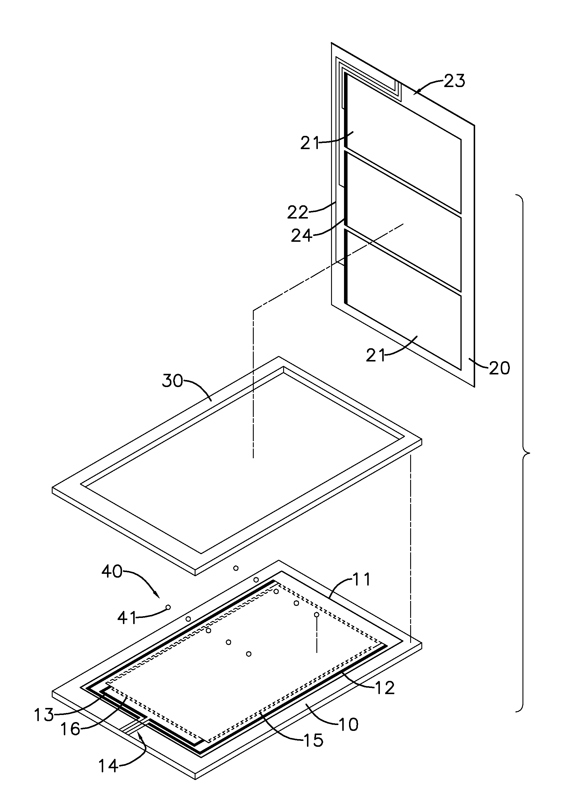
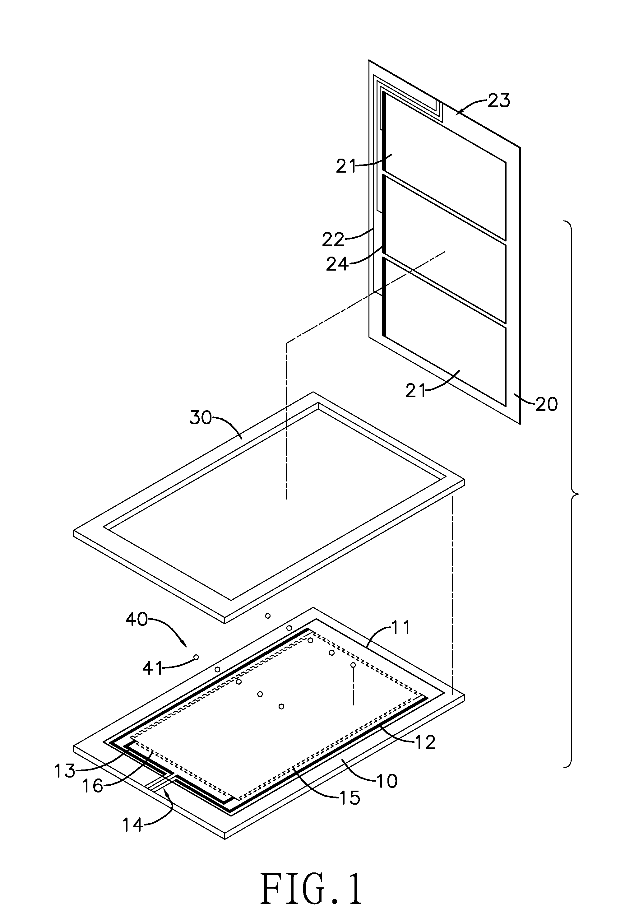
[0033]With reference to FIG. 1, a compound resistive touch panel in accordance with a first embodiment of the present invention has a first substrate (10), a second substrate (20), an insulation layer (30) and a separating layer (40).

[0034]The first substrate (10) and the second substrate (20) are oppositely mounted. The insulation layer (30) and the separating layer (40) are mounted between the first substrate (10) and the second substrate (20).

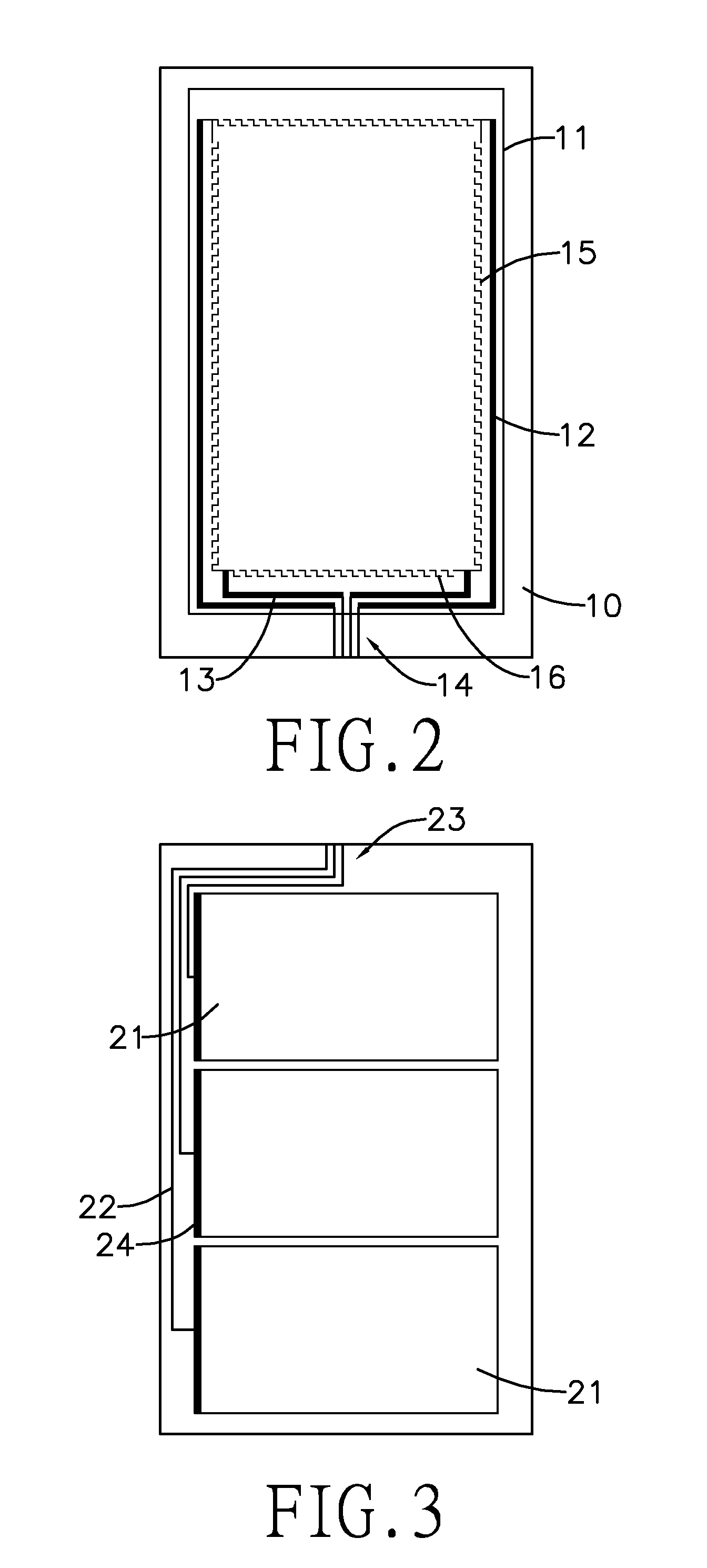
[0035]With reference to FIG. 2, the first substrate (10) has a first transparent electrode (11), two long electrodes (12), two short electrodes (13), a plurality first leading lines (14), two bands of long resistive layers (15) and two bands of short resistive layers (16).

[0036]The first substrate has a top surface, and the first transparent electrode (Indium Tin Oxide, ITO) (11) is mounted on the top surface. The first transparent electrode (11) occupies most area of the top surface of the first substrate (10). In the present embodiment, th...


PUM


Abstract

A hybrid touch panel has a first substrate, a second substrate, and an insulation layer and a separating layer sandwiched between the first and second substrates. The first substrate has a first transparent electrode mounted thereon. A plurality of first electrodes are respectively mounted alongside edges of the first transparent electrode and are respectively connected with a plurality of first leading lines. The second substrate has a plurality of juxtaposed second transparent electrodes respectively corresponding to the first transparent electrode, a plurality of second electrodes respectively mounted on the second transparent electrodes and connected with a plurality of wires and second leading lines. Each second transparent electrode accompanying with the first transparent electrode forms an active areas. Accordingly, a multi-area touch panel can be constructed to enable a more smooth and flexible operation.

Description

BACKGROUND OF THE INVENTION[0001]1. Field of the Invention[0002]The present invention is related to a touch panel, and more particularly to a hybrid touch panel having a single panel with a plurality of active areas.[0003]2. Description of the Related Art[0004]Touch panels have been extensively applied to various walks of life nowadays. Related techniques are constantly upgraded and introduced. Current touch panels in the market are classified into resistive touch panels, capacitive touch panels, surface acoustic wave touch panels, infrared touch panels and so forth. Speaking of the market share, resistive touch panels rank top due to simple structure and low cost, capacitive touch panels rank second and take few tens of the market share, and the market shares of the rest of touch panels are really not so prominent. Resistive touch panels are advantageous in a simple structure and low cost but disadvantageous in single-touch detection and poor durability. Dominated by cost concern, ...

Claims


Application Information

Patent Timeline
Patent Type & Authority Applications(United States)
IPC IPC(8): G06F3/041
CPCG06F3/045
Inventor HSIH, LUNG-SHENGHSU, JANE
Owner MINLEAD
Learn More