Fixing structure for dissipation device

a technology of dissipation device and fixing structure, which is applied in the direction of insulated conductors, power cables, semiconductor/solid-state device details, etc., can solve the problems of increasing the space or a higher space, and the contact pressure of the dissipation device is not easily adjusted,

Inactive Publication Date: 2005-02-22
QUANTA COMPUTER INC
View PDF7 Cites 28 Cited by
  • Summary
  • Abstract
  • Description
  • Claims
  • Application Information

AI Technical Summary

Benefits of technology

It is therefore an objective of the present invention to provide a fastening structure

Problems solved by technology

Because of requirements for lighter, thinner, shorter, and smaller portable electronic apparatuses, many challenges arise in the manufacturing of electronic components and assembly of apparatuses.
However, this method occu

Method used


Image

  • Fixing structure for dissipation device
  • Fixing structure for dissipation device
  • Fixing structure for dissipation device

Examples


Embodiment Construction

Reference will now be made in detail to the present preferred embodiments of the invention, examples of which are illustrated in the accompanying drawings. Wherever possible, the same reference numbers are used in the drawings and the description to refer to the same or like parts.

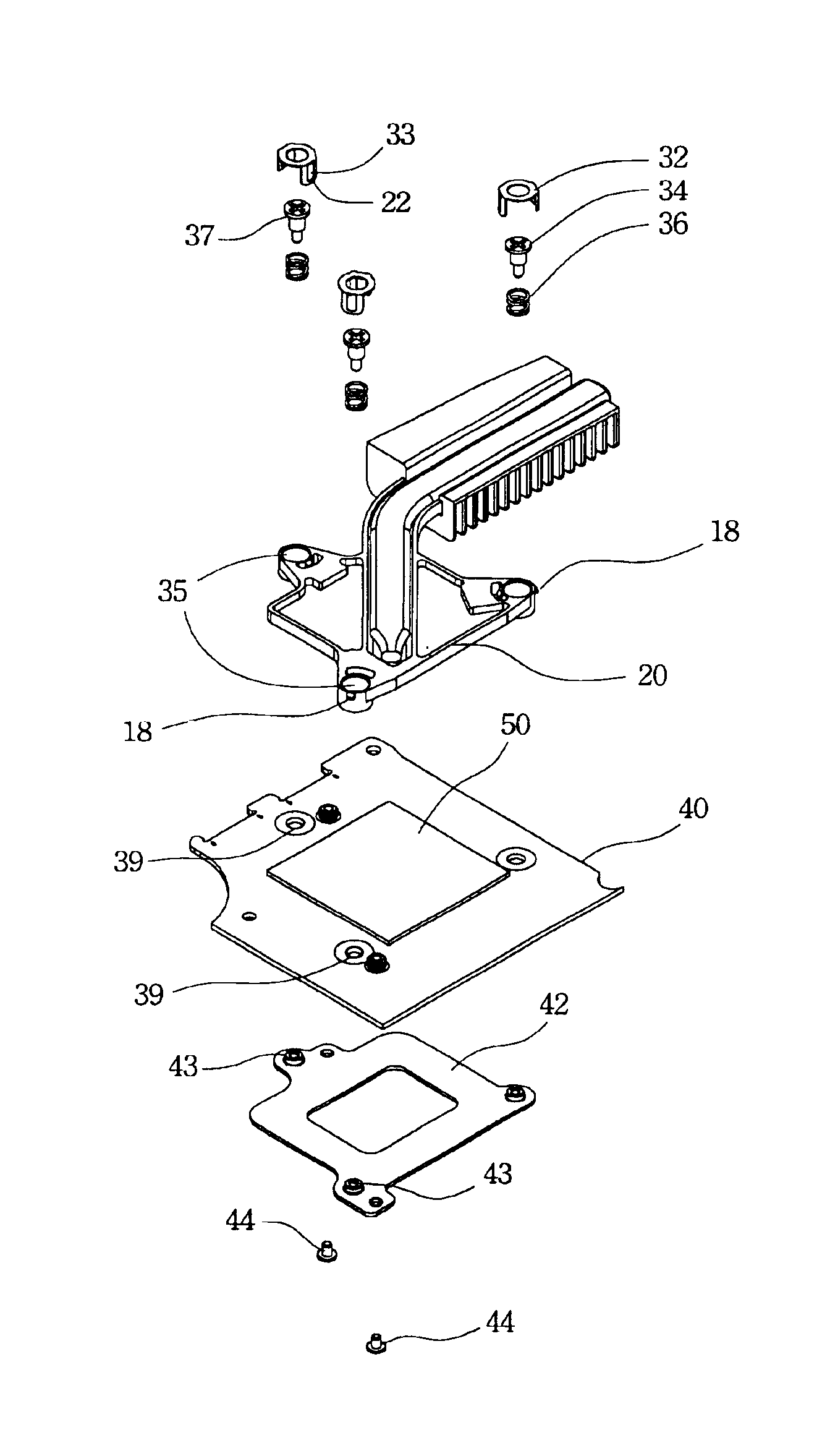
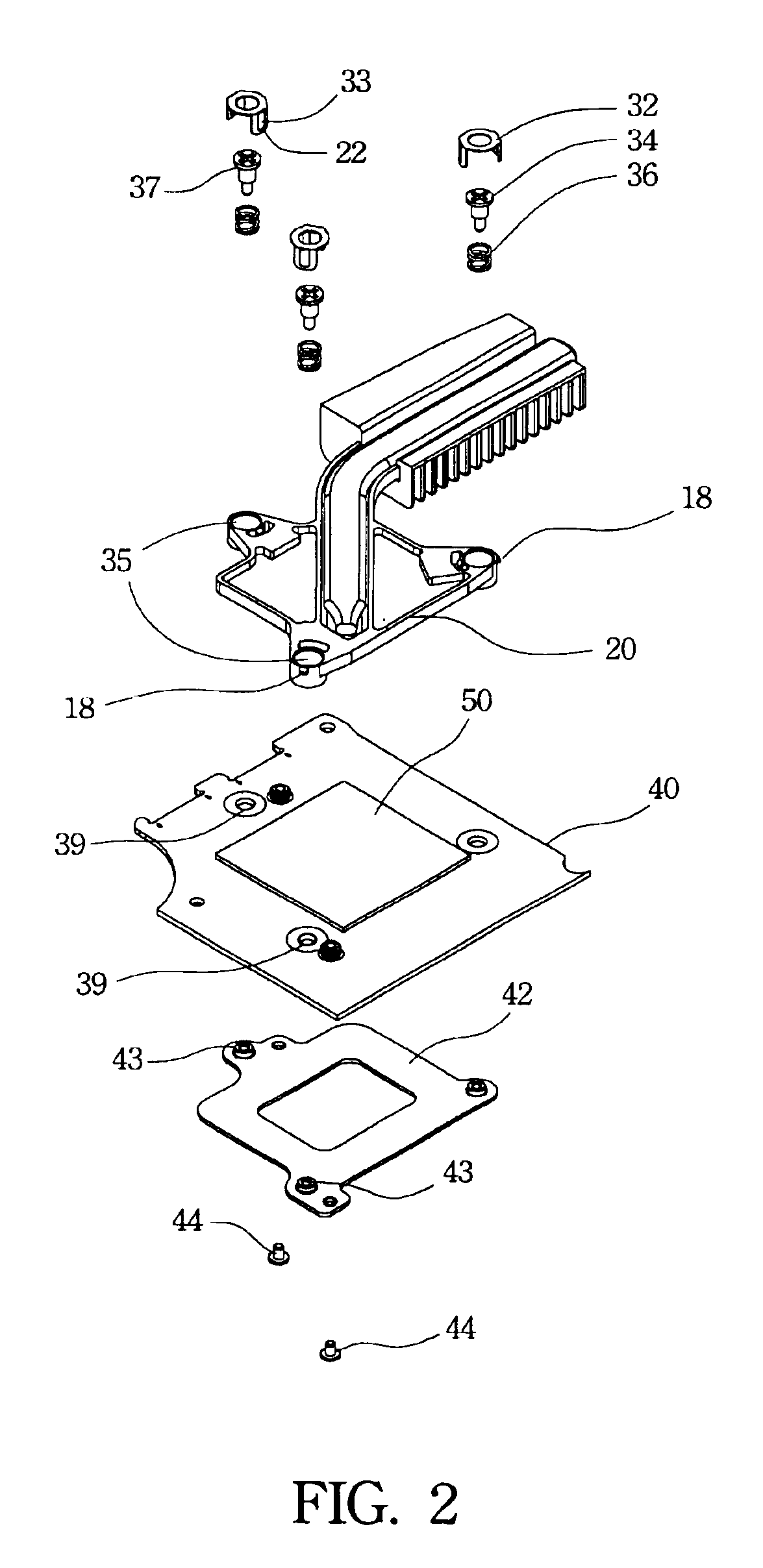
The present invention is directed to solving the space limitation issue while a heat dissipation device is fixed by bolt fastening. In one preferred embodiment of present invention, a screw cap is employed to keep a fastening screw and an elastic element in an assembly hole so as to minimize the space for assembly and prevent the fastening screw and the elastic element from slipping out of the assembly hole. The cap can avoid an unbalancing stress between the heat dissipation device and a component during the assembly process.

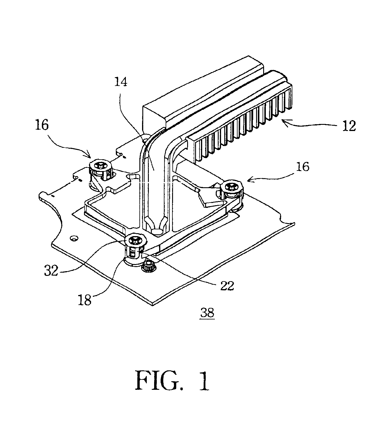
FIG. 1 illustrates a perspective view of a fastening structure for heat dissipation device according to one preferred embodiment of this invention. The preferred embodiment includes a...


PUM


Abstract

A fastening structure for dissipation device has a metal plate with at least one screw hole, a screw with an engagement part, an elastic element, and a screw cap. The screw and the elastic apparatus are assembled in the screw hole. The screw cap, whose clamp structures are fastened to the outside of the screw hole, limits movement of the screw and the elastic element in the screw hole. The screw is allowed to move upward and downward within a predetermined scope.

Description

BACKGROUND OF THE INVENTION1. Field of InventionThe present invention relates to a fastening structure. More particularly, the present invention relates to a fastening structure for a dissipation device.2. Description of Related ArtAs the information technology and computer industry advances, portable electronic apparatuses, such as notebook computers, and other precise instruments are widely used. Owing to demands for convenience and practicality, the portable electronic product is designed to be lighter, thinner, shorter, and smaller. For example, a notebook PC is required to be lighter, thinner and powerful in computing performance.Because of requirements for lighter, thinner, shorter, and smaller portable electronic apparatuses, many challenges arise in the manufacturing of electronic components and assembly of apparatuses. For example, there are several fastening methods for a dissipation device, such as bolt fastening with a spring and bolt fastening with an elastic plate. In ...

Claims


Application Information

Patent Timeline
IPC IPC(8): F16B5/02H01L23/40H01L23/427H01L23/34
CPCF16B5/0266H01L23/4006H01L23/427H01L2924/0002H01L2924/00
Inventor YANG, KUO-CHANG
Owner QUANTA COMPUTER INC
Why Eureka
Try Eureka