Microstructured optical fiber

a microstructured, optical fiber technology, applied in the direction of optical fiber with multi-layer core/cladding, optical waveguide light guide, instruments, etc., can solve the problems of reducing increasing the bending loss, increasing the sensitivity to the fluctuation of the structural parameters of the effective core area, etc., to reduce the excess transmission loss, high bit rate, and optical fiber robust

Inactive Publication Date: 2005-02-22
SUMITOMO ELECTRIC IND LTD
View PDF11 Cites 14 Cited by
  • Summary
  • Abstract
  • Description
  • Claims
  • Application Information

AI Technical Summary

Benefits of technology

The present invention has been made in view of the above and it is an object of the present invention to provide an optical fiber which can realize all of the large negative chromatic dispersion, the large effective core area and the small bending loss simultaneously.
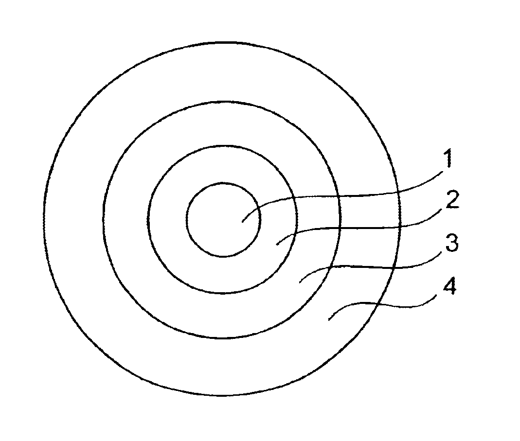
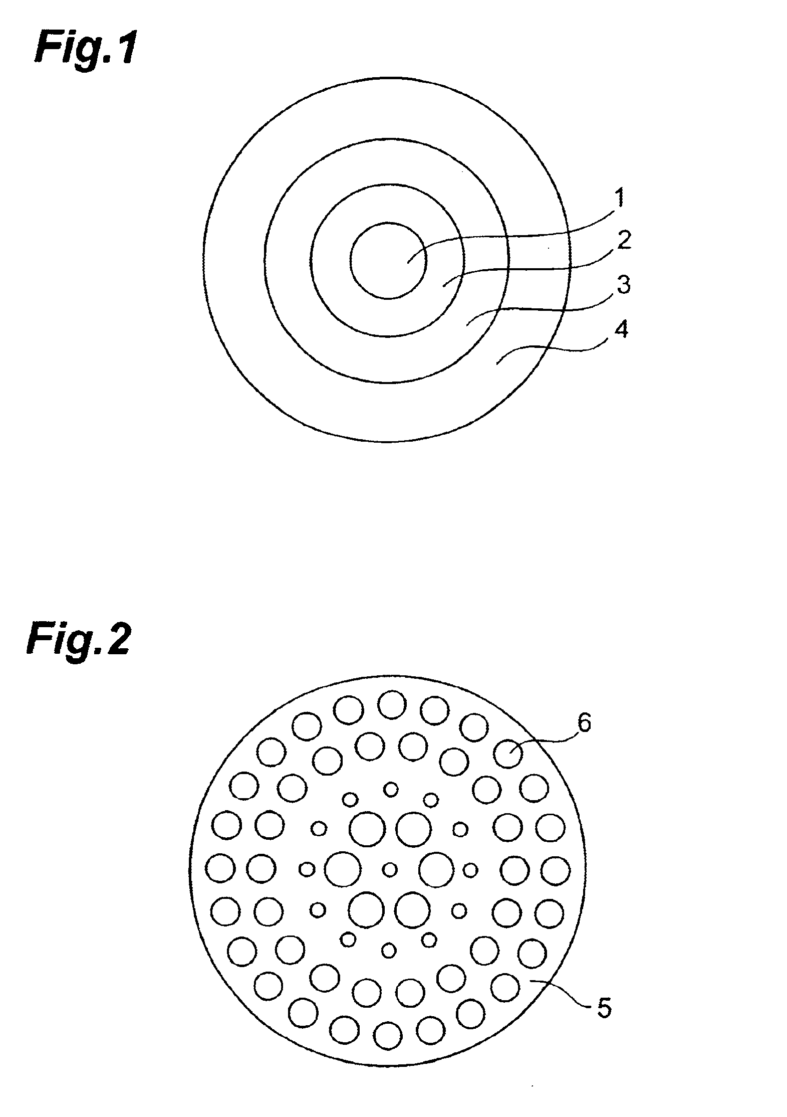
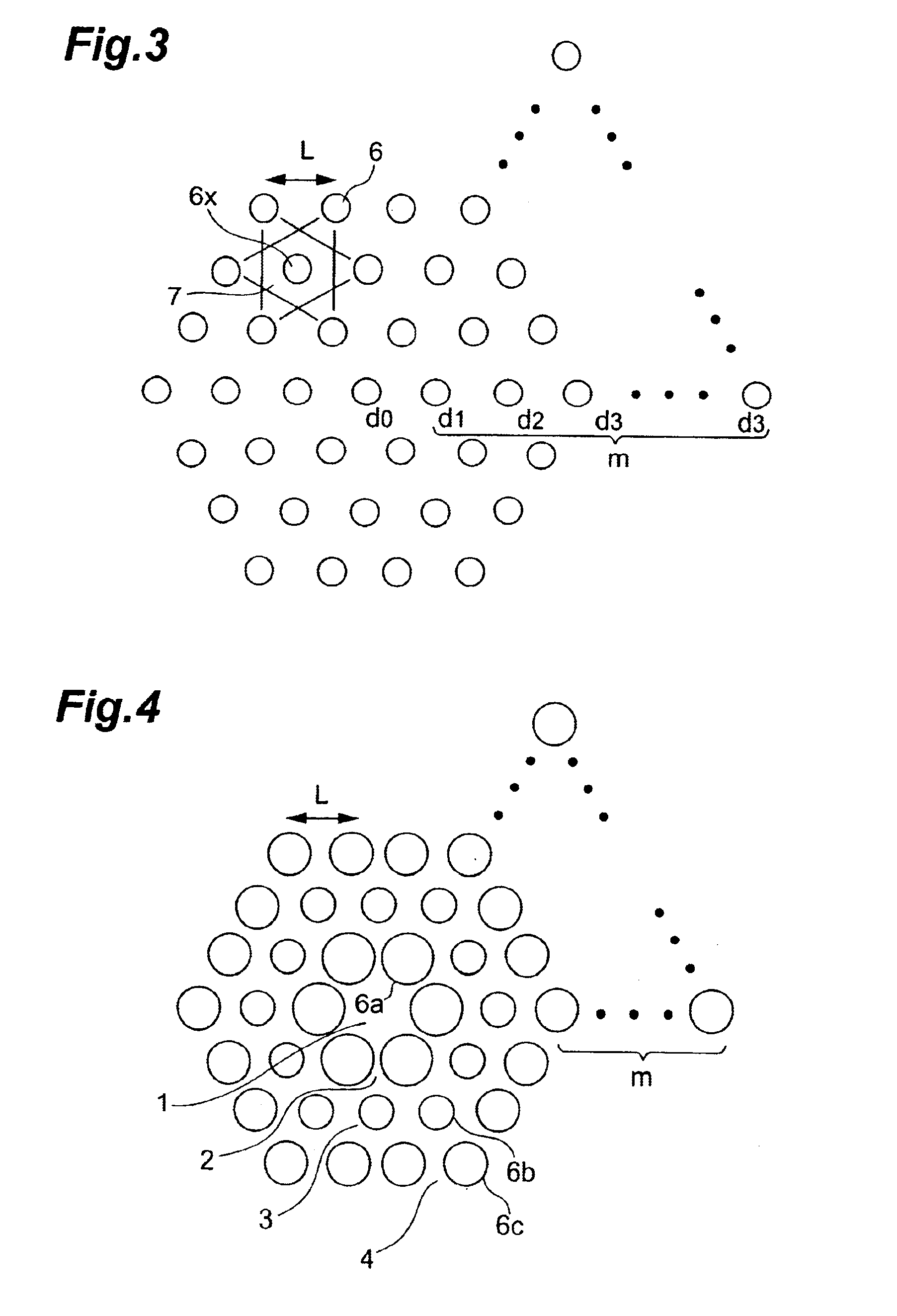
When the sub medium regions are arranged in a plurality of cladding regions, it is preferable to make the cross-sectional area ratio of the sub medium regions in each cladding region differs from that in each adjacent cladding region. Here, the cross-sectional area ratio is a value obtained by dividing the sum of areas which a certain medium occupies in a certain region by the area of the region. It will also be called sub medium occupying ratio. In this manner, by increasing or decreasing the cross-sectional area of the sub mediums per a unit cross-sectional area, the mean refractive index of the region including the sub medium can be determined and hence, the magnitude relationship of the mean refractive indices of respective regions can be easily determined.

Problems solved by technology

However, although the optical fiber disclosed in the above-mentioned publication increases the negative chromatic dispersion compared to the optical fiber having the uniform cladding structure, the optical fiber suffers from drawbacks such as the lowering of the effective core area, the increase of the bending loss and the increase of sensitivity to the fluctuation of the structural parameters of the effective core area.

Method used


Image

  • Microstructured optical fiber
  • Microstructured optical fiber
  • Microstructured optical fiber

Examples


second embodiment

In this manner, since the optical fiber has the large effective core area, the occurrence of the nonlinear optical phenomena can be suppressed whereby the transmission quality can be enhanced.

FIG. 13 is a view which shows the calculated result of the effective core area when the respective pitches L of the examples 2, 3 and the comparison example 2 are changed in a comparison form. Here, the pitches L are set such that the effective core area Aeff at the wavelength of 1550 nm becomes 12 μm2in all of the examples 2, 3 and the comparison example 2. That is, the pitch values are respectively set to 1.33 μm in the example 2, 1.53 μm in the example 3 and 1.21 μm in the comparison example 2.

Focusing on the change of the effective core area Aeff at the wavelength λ=1550 nm, with respect to the magnitude of the change of the effective core area Aeff relative to the change of the wavelength, the example 2 has the smaller magnitude of the change of the effective core area Aeff than the compa...

third embodiment

Accordingly, the optical fiber of the third embodiment can reduce the sensitivity of the structural chromatic dispersion to the shape of the voids. Further, with the introduction of the voids, the bending loss can be reduced. In general, when the chromatic dispersion is displaced from a given value, the deterioration of the transmission quality caused by the residual dispersion in the transmission path occurs and hence, the high fabrication accuracy is required with respect to the chromatic dispersion. On the other hand, the bending loss is only required to be lower than a given threshold value, no high fabrication accuracy is required with respect to the bending loss. In the optical fiber of this embodiment, although the bending loss depends on the shape of voids, the chromatic dispersion does not depend on the shape of voids and hence, the demand for the fabrication technique with respect to the accuracy of the shape of voids can be alleviated.

In any one of examples 4 to 6, as in ...


PUM


Abstract

In an optical fiber including a core region and cladding regions of not less than three layers which surrounds the core region in order, each of said cladding regions has a mean refractive index different from those of the adjacents regions,at least one of the cladding regions has a lower mean refractive index than both adjacent regions, and at least one cladding region is provided with a plurality of sub medium regions each having a refractive index lower than a main medium constituting this cladding region.

Description

BACKGROUND OF THE INVENTION1. Field of the InventionThe present invention relates to an optical fiber which can be suitably used as an optical transmission path and a dispersion compensator.2. Related Background ArtFIG. 22 is a cross-sectional view of an optical fiber including a so-called microstructure which has been known conventionally. As shown in FIG. 22, this optical fiber has a cross-sectional structure having a large number of voids (vacant holes) 62 in a silica glass 61. A central portion in cross section having no voids 62 constitutes a core region 63 and a portion, surrounding the core region 63, which has a large number of the voids 62 constitutes a cladding region 64.The principle of light confinement of the optical fiber having such a microstructure is explained qualitatively using a concept called effective refractive indices (for example, T. A. Birks et al. Optics Letters Vol. 22 p.961 (1997)). Due to the existence of the microstructure, in a strict sense, the refra...

Claims


Application Information

Patent Timeline
Patent Type & Authority Patents(United States)
IPC IPC(8): G02B6/02
CPCG02B6/02028G02B6/02261G02B6/0228G02B6/02347G02B6/03644G02B6/02357G02B6/02361G02B6/02366G02B6/02352
Inventor HASEGAWA, TAKEMISASAOKA, EISUKENISHIMURA, MASAYUKI
Owner SUMITOMO ELECTRIC IND LTD
Why Eureka
Try Eureka