
Spa cover lifter apparatus and method

a lifter and spa technology, applied in the field of hot tubs and spas, can solve the problems of large complexity of the mechanism, difficulty in adapting to the design, and difficulty in sliding a large volume of the cover by single users, and achieve the effect of reducing the effort required

Active Publication Date: 2005-03-01
WATKINS MFG
View PDF18 Cites 16 Cited by
  • Summary
  • Abstract
  • Description
  • Claims
  • Application Information

AI Technical Summary

Benefits of technology

One object of the present invention is reduce the effort required to remove a spa cover from a spa.
Another object is to protect expensive spa covers by simplifying the removal process thereof from a spa.
Yet another object is to reduce the expense of heating water in spas by promoting the use of spa covers that are easily removed by one person.
A further object is to increase the safety of using a cover removal apparatus.
Still another object is to fully support a spa cover in a compact manner thereby minimizing the space taken by the stowed cover following the removal process.

Problems solved by technology

Such mechanisms vary widely in complexity, ease of operation and cost of manufacturing.
Because of the arrangement of the mounting arms and their attachment to the spa cover, the design is not easily adaptable for use with spa covers that fold back to expose only a portion of the spa.
Because the Forrest device requires that the entire spa cover be moved rearward onto the movable frame, a single user could find it difficult to slide a large heavy cover.
While most of the above noted designs assist in the removal process of a spa cover from a spa, they typically do not provide a simple, safe, inexpensive and adjustable means to remove and support the spa cover in a compact position which allows unimpeded access to the spa.

Method used


Image

  • Spa cover lifter apparatus and method
  • Spa cover lifter apparatus and method
  • Spa cover lifter apparatus and method

Examples


Embodiment Construction

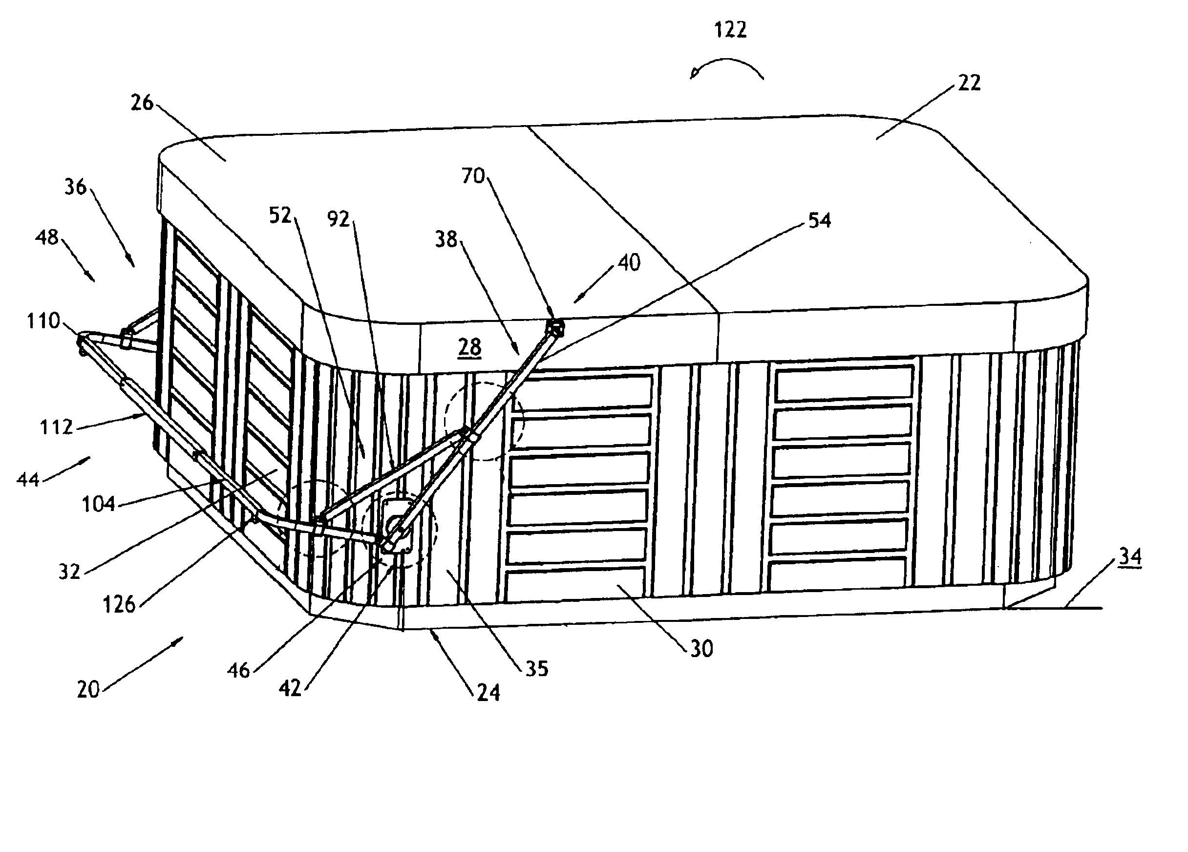
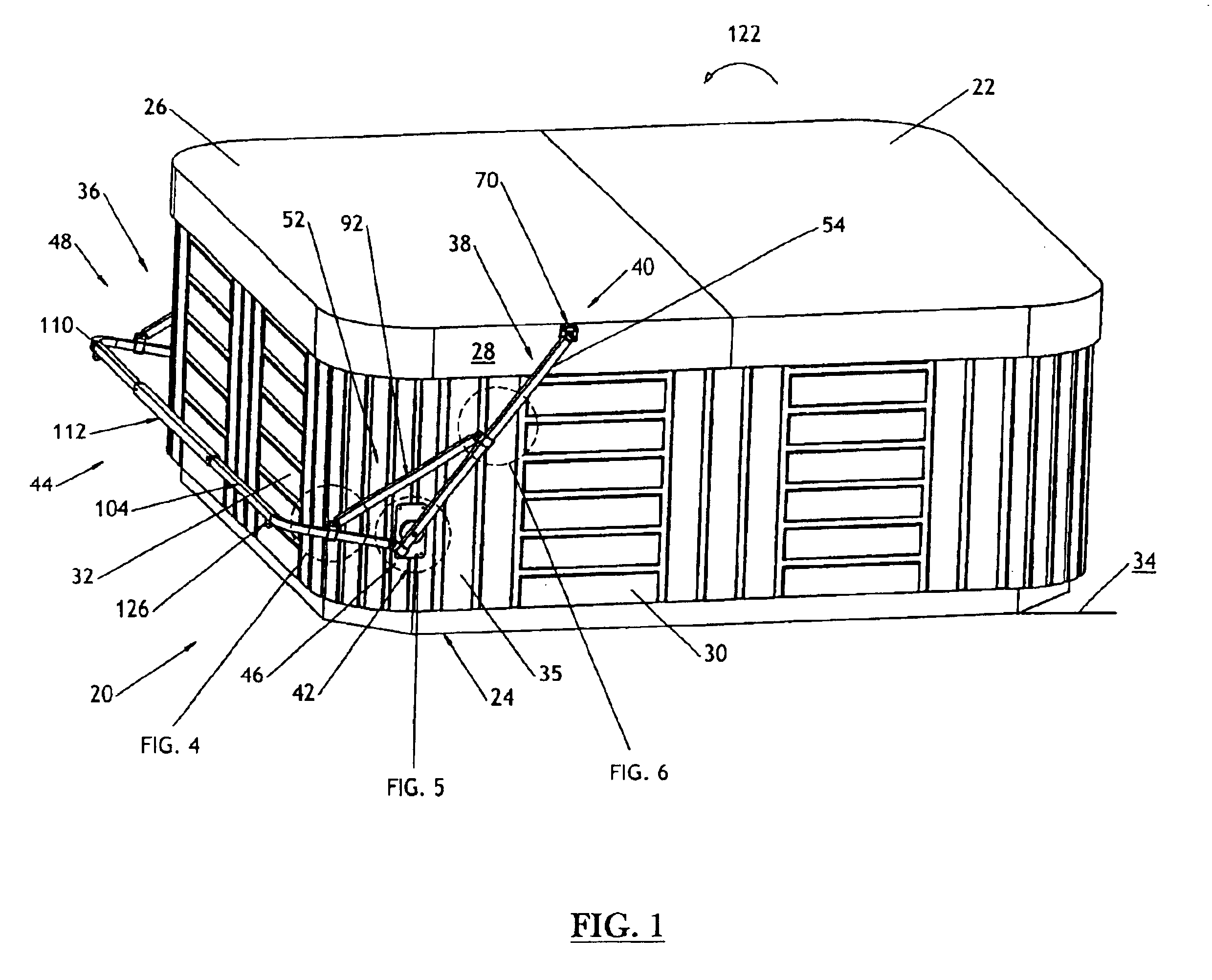
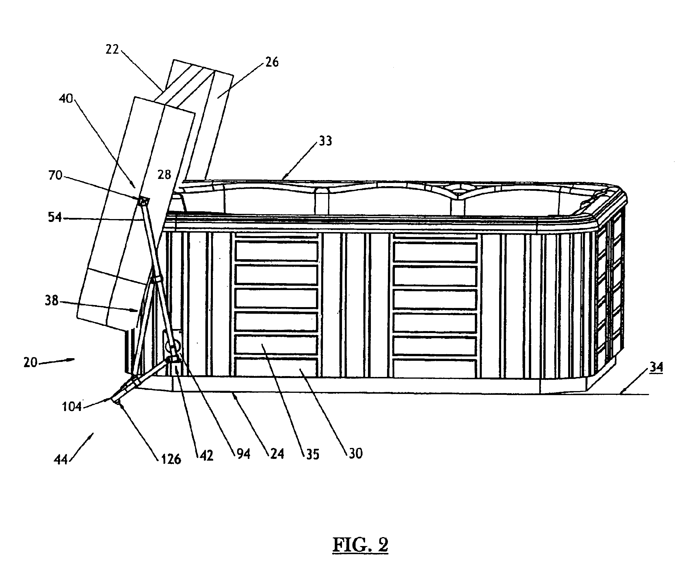
FIGS. 1 through 8 show a preferred embodiment of a spa cover lifter 20. The spa cover lifter 20 is provided to assist a person in the repositioning and removal of a spa cover 22 from a spa 24. Typically, a spa cover 22 is constructed to include opposing left and right cover side surfaces 26 and 28. Additionally, spas are typically arranged to include a cabinet 30 having a back spa side 32 disposed between opposing left and right spa sides 33 and 35. Generally, such spas, and the cabinets thereof, are supported from a substantially flat supporting surface 34 or floor.

In the present invention, the spa cover lifter 20 is symmetrically constructed with the left side being a mirror image of the right side. Accordingly, only the components of the right side are discussed in detail and illustrated in the drawings. The spa cover lifter 20 comprises opposing left and right side arm supports 36-38 spaced apart to receive opposing left and right cover side surfaces 26-28 between the same. Each...


PUM


Abstract

A spa cover lifter comprising opposing left and right side arm supports spaced apart to receive opposing left and right cover side surfaces between the same. Each side arm support has an upper end adapted to rotatably support a portion of the spa cover and an opposing lower end. Each side arm support is rotatably mounted to a spa side. Extending from the right side arm support, around the back spa side, to the opposing left side arm support is a lower linking member having opposing ends spaced apart to pivotally attach to the respective spaced apart left and right side arm supports. The linking member can pivot relative to the side arms, about a substantially horizontal axis to define a linking member pivot angle which is the angle between each side arm support and the linking member. The pivotal attachment point of the lower linking member to the respective side arm support is adjacent the respective lower end thereof. To maintain the relative angle between each side arm support and the linking member, an adjustable bracing extends between each side arm support and the linking member. The relative position between each side arm support and the linking member is adjustable.

Description

BACKGROUNDThis invention relates generally to hot tubs and spas, and more particularly to removal systems adapted for lifting and removing spa covers therefrom.Spa cover removal systems and mechanisms are known in the art. Such mechanisms vary widely in complexity, ease of operation and cost of manufacturing. In recent years, the rise in popularity of spas, commonly referred to as hot tubs, has hastened the development of spa covers and removal apparatus therefor. One early design for cover removal is disclosed in U.S. Pat. No. 4,857,374 issued to Perry (Gary L.) in 1989. The Perry design employs gas springs that extend from the sides of a spa to a spa cover that is hinged to the rear of the spa. In this way, the gas springs assist the user to pivot the cover to a vertical position, away from the top of the spa.U.S. Pat. No. 4,853,985 issued to Perry (Cliff R.) in 1989 shows a cover assembly for use with a spa. The cover assembly includes a cover member mounted for rotational moveme...

Claims


Application Information

Patent Timeline
Patent Type & Authority Patents(United States)
IPC IPC(8): E04H4/08E04H4/00
CPCE04H4/084
Inventor PERRY, GARY L.
Owner WATKINS MFG
Learn More