Manipulation unit

a technology of manipulation unit and manipulation device, which is applied in the direction of mechanical control devices, instruments, prostheses, etc., can solve the problems of time-consuming and labor-intensive precision control of positioning control, affecting the operation of the machine, and affecting the accuracy of positioning control, so as to achieve a simple mechanism and reduce friction. the effect of friction

Inactive Publication Date: 2005-03-01
SEIKO EPSON CORP
View PDF11 Cites 66 Cited by
  • Summary
  • Abstract
  • Description
  • Claims
  • Application Information

AI Technical Summary

Benefits of technology

This makes it possible to reduce friction between the projecting portions and the guide grooves even when the former comes into contact with the latter, thus permitting smooth execution of linear motion of the moving blocks.
The invention also provides a manipulation unit, wherein the universal joints have stepped bearing screws screwed i

Problems solved by technology

However, securing/gripping hands utilizing parallel link mechanisms have suffered from the problem that they could not permit 3-degrees-of-freedom because they were joined to an arm with only one or 2-degrees-of-freedom, and this has rendered precision control of their positioning time-consuming.
Further, the method of using gearwheels to re

Method used


Image

  • Manipulation unit
  • Manipulation unit
  • Manipulation unit

Examples


first embodiment

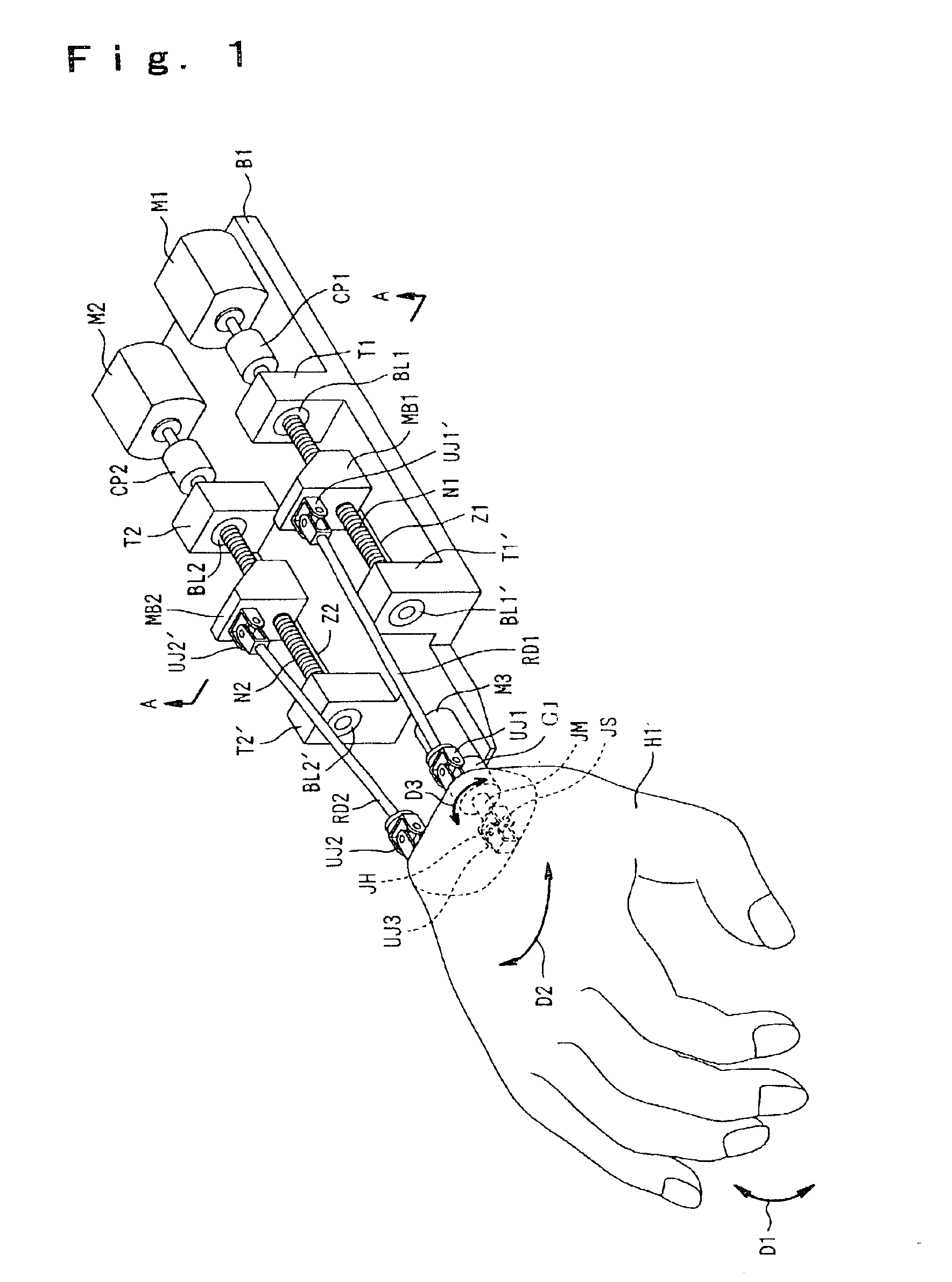
FIG. 1 is a perspective view showing a general configuration of a robot hand according to the present invention.

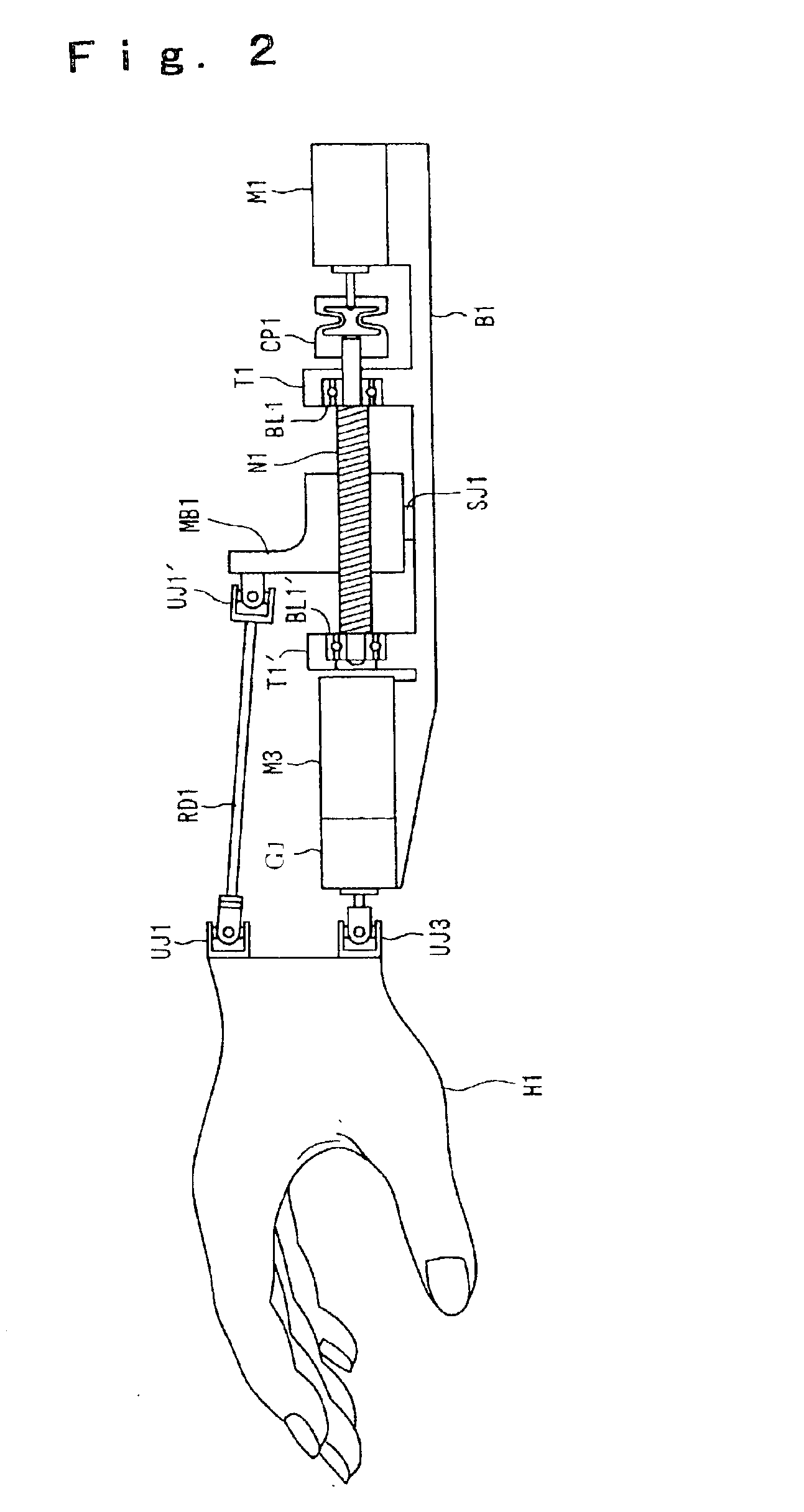
FIG. 2 is a side view showing a general configuration of a robot hand according to the first embodiment of the present invention.

FIG. 3 is a cross-sectional view of a rotation prevention mechanism for moving blocks in the robot hand according to the first embodiment of the present invention.

FIG. 4 is an exploded perspective view showing the structure of universal joints in the robot hand according to the first embodiment of the present invention.

FIG. 5(a) is a diagram showing coordinates of the various points, for the purpose of explicating the drive method for a robot hand according to an embodiment of the present invention. FIG. 5(b) is a diagram showing the coordinates after a rotation about the x-axis has been made.

FIG. 6 is a diagram showing coordinates of the various points after a rotation has been made, for the purpose of explicating the drive method for a robot ha...

second embodiment

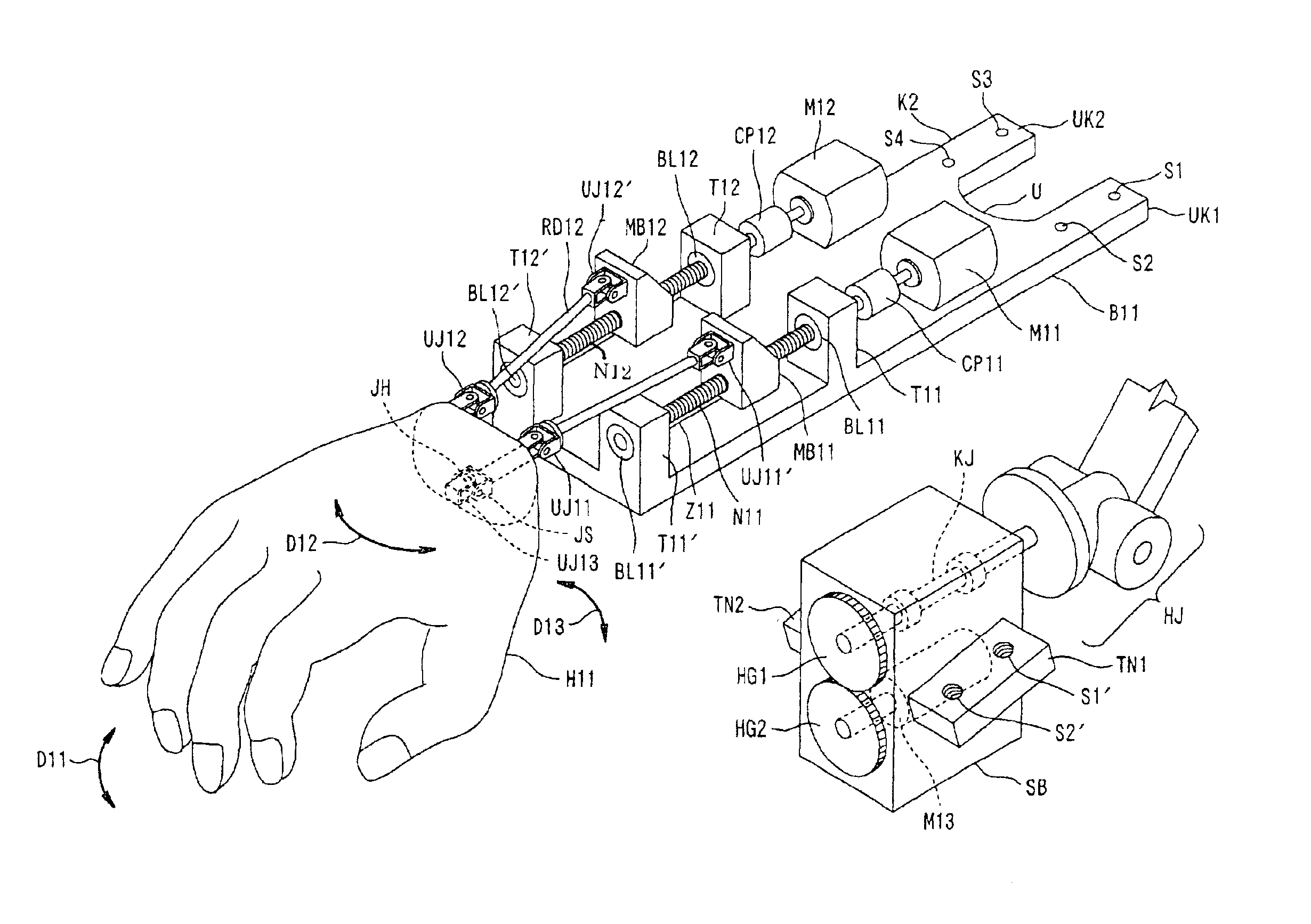
FIG. 7 is a perspective view showing a general configuration of a robot hand according to the present invention.

FIG. 8 is a side view showing a general configuration of a robot hand according to the second embodiment of the present invention.


PUM


Abstract

3-degrees-of-freedom universal joints UJ1 and UJ2 for allowing the hand H1 to make up-down swing motions D1 and side-to-side swing motions D2 are joined to the top right and left parts, respectively, of the wrist portion of the hand H1, and a 2-degrees-of-freedom universal joint UJ3 for allowing the hand H1 to make twisting rotations D3 is joined to the wrist portion of the hand H1 so as to serve as the center of 3-degrees-of-freedom.

Description

DETAILED DESCRIPTION OF THE INVENTION1. Field of the InventionThe present invention relates to manipulation units and is particularly suited to application in robot hands, manipulators and the like.2. Description of the Related ArtIndustrial robots have conventionally been equipped with a securing / gripping hand utilizing parallel link mechanisms, such as described for instance in Laid-Open Japanese Patent Application No. 9-285874. Further, there have been humanoid robots having a single-point intersection type wrist mechanism allowing the 3 axes of the wrist joint to intersect at a single point by means of gearwheels, as described in the Robot Handbook (Corona Publications).However, securing / gripping hands utilizing parallel link mechanisms have suffered from the problem that they could not permit 3-degrees-of-freedom because they were joined to an arm with only one or 2-degrees-of-freedom, and this has rendered precision control of their positioning time-consuming.Further, the meth...

Claims


Application Information

Patent Timeline
IPC IPC(8): A61F2/50A61F2/58B25J15/00B25J17/02F16D3/16F16D3/40A61F2/70
CPCA61F2/585B25J15/0009B25J17/0266F16D3/40B25J9/0042B25J17/0275A61F2/70Y10T74/20335Y10T74/20329Y10T74/20305
Inventor SHINOZAKI, JUNICHIRO
Owner SEIKO EPSON CORP
Why Eureka
Try Eureka