Method and apparatus for tracking documents in a workflow

Inactive Publication Date: 2005-03-01
RICOH KK
View PDF33 Cites 265 Cited by
  • Summary
  • Abstract
  • Description
  • Claims
  • Application Information

AI Technical Summary

Benefits of technology

A workflow system and method comprise one or more sensors disposed about an area of the workflow. The sensors detect proximity of a document as it is moved about in the area of the workflow. The information collected is associated with information relating to

Problems solved by technology

Any substantial project is likely

Method used


Image

  • Method and apparatus for tracking documents in a workflow
  • Method and apparatus for tracking documents in a workflow
  • Method and apparatus for tracking documents in a workflow

Examples


Embodiment Construction

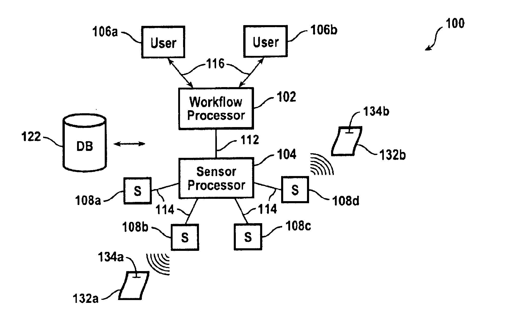
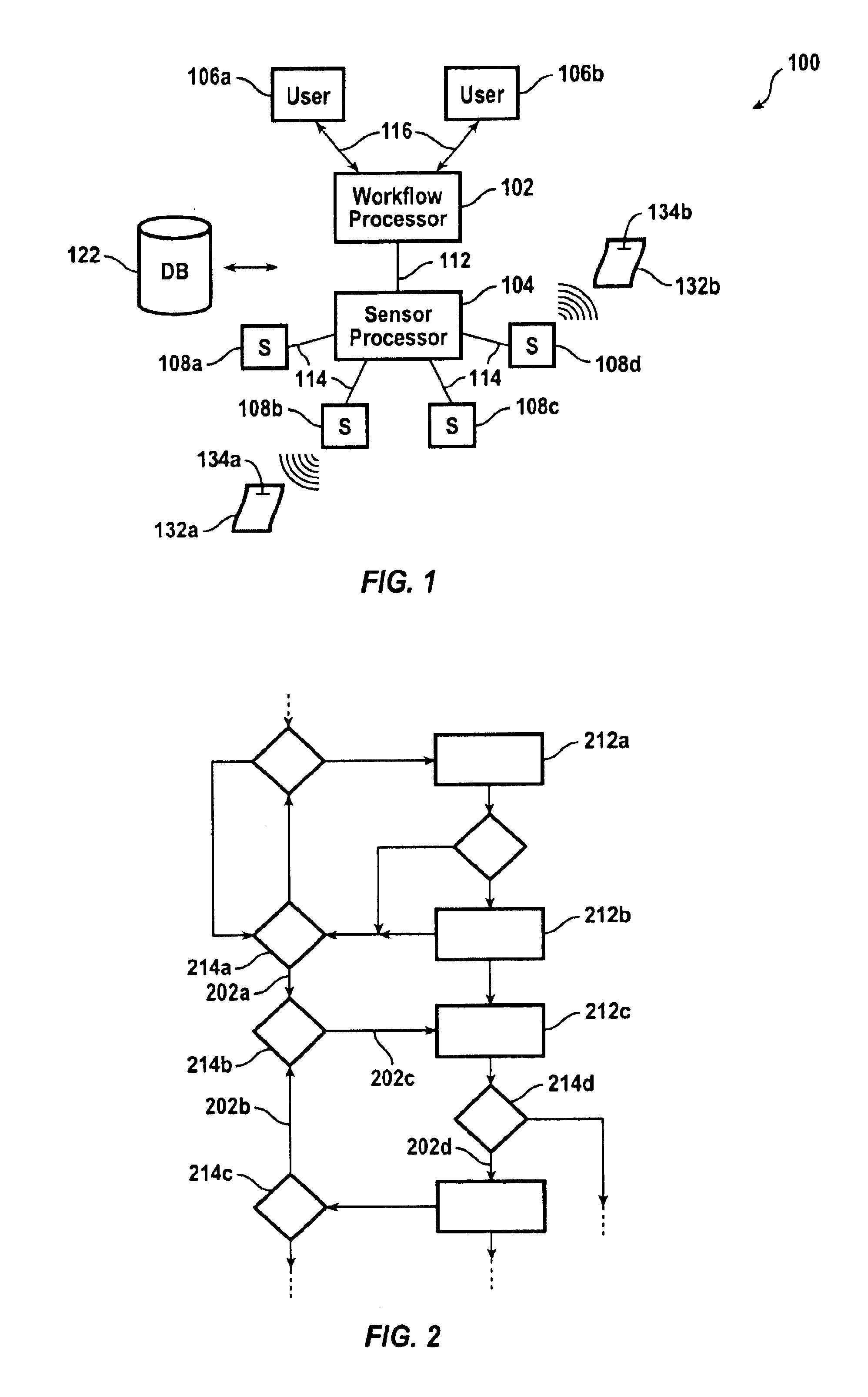
FIG. 1 is a highly generalized block diagram of a document workflow system in accordance with an embodiment of the present invention. A workflow processor 102 represents the component that provides the functionality commonly found in typical workflow systems. Typically, this includes a computer component, such as a personal computer, running appropriate software. It can be appreciated that the workflow processor can be any appropriate computing configuration or platform. Some functions provided by a workflow system include identifying documents to be routed in the workflow. The workflow includes a workflow graph which identifies the paths along which the participating documents are to be routed.

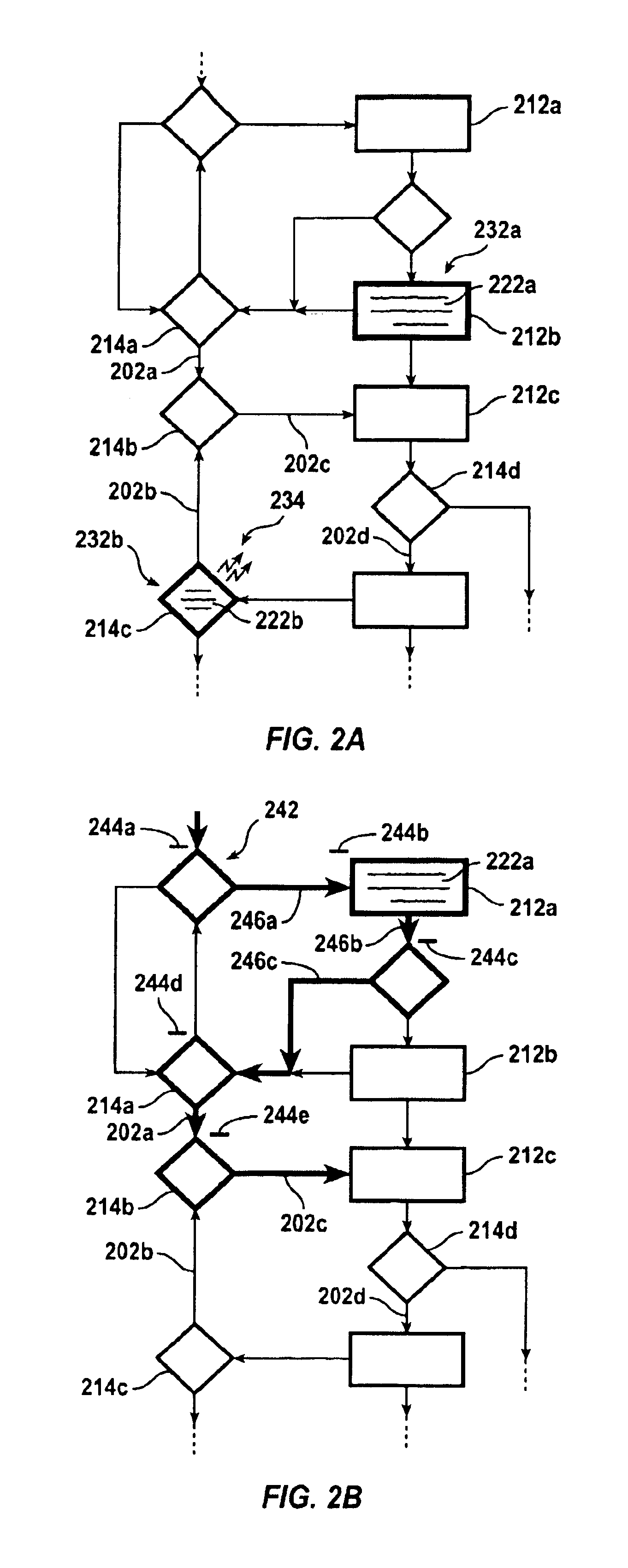
Referring to FIG. 2 for a moment, a portion of a typical workflow is illustrated. This representation is an exemplar of a graphical representation of a workflow, used to illustrate aspects of embodiments of the present invention. It can be appreciated that actual workflow systems will include...


PUM


Abstract

A workflow system and method include tracking the physical movement of documents. The information of the physical movement is incorporated with the flow graph of a workflow. A display of the workflow can then be enhanced by the information relating to the physical movement of the document.

Description

BACKGROUND OF THE INVENTIONThe present invention relates generally to workflow systems and more particularly to tracking documents in a workflow system.During the course of running a business, there are many steps and people involved in each endeavor. Accompanying this activity might be the flow of large numbers of documentation. For example, documents generated by a person or by people in a workgroup often require distribution to other people in the company or among different groups of people. Workflow systems provide a way for managing the flow of numerous documents during the course of a project.Any substantial project is likely to produce volumes of paperwork. Effective management of a large-scale project requires up to date information. In the case of documents, it is important to know who has what document, how far along a document is in the review process, and so on. This can facilitate identifying critical paths and bottlenecks. It is therefore desirable to be able to enhanc...

Claims


Application Information

Patent Timeline
IPC IPC(8): G06Q10/00G01S13/74G06K17/00G06Q10/10
CPCG06Q10/10
Inventor HULL, JONATHAN J.GRAHAM, JAMEYLEE, DAR-SHYANGSEGAWA, HIDEKI
Owner RICOH KK
Why Eureka
Try Eureka