Range evaluation system

a range evaluation and evaluation system technology, applied in the field of range evaluation system, can solve the problems of poor audio quality, poor audio quality, and inability to perform meaningful aar, and achieve the effect of improving quality and efficiency

Inactive Publication Date: 2006-08-17
DEPT OF THE ARMY
View PDF6 Cites 5 Cited by
  • Summary
  • Abstract
  • Description
  • Claims
  • Application Information

AI Technical Summary

Benefits of technology

[0011] Accordingly, one object of the present invention is to provide a more effic...

Problems solved by technology

Currently, these tools are crude and inadequate to perform a meaningful AAR.
The quality of the recording is often poor because the cassette tape recorder records ambient noise and conversations in addition to the radio communications.
The disadvantages of this method are the poor audio quality and the inherent limitations associated with using an audio record to recreate a dynamic action sequence.
Standard 1st Generation thermal imagers do not offer a video line output.
Therefore, unless the systems are modified, the imagery from the systems cannot be recorded to document the exerc...

Method used


Image

  • Range evaluation system
  • Range evaluation system
  • Range evaluation system

Examples


Embodiment Construction

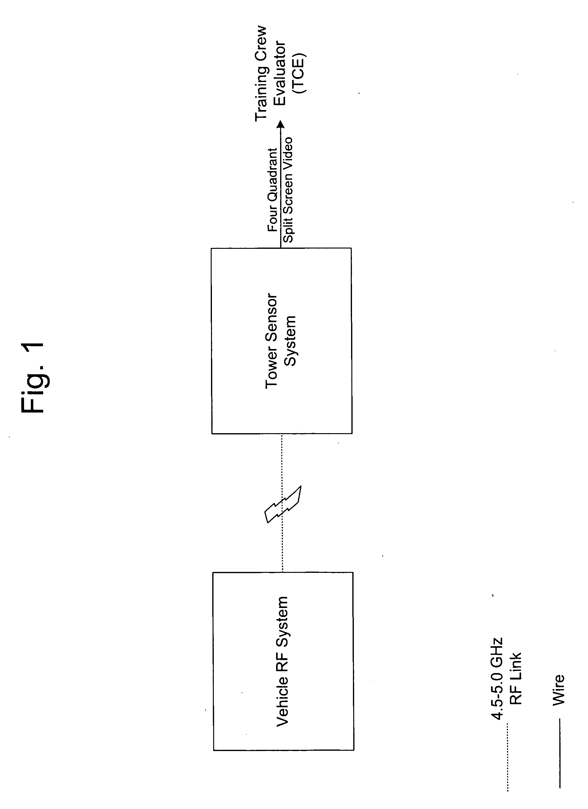
[0020] As shown by the general overview of the present invention in FIG. 1, the system of the present invention is divided into two primary subsystems the Vehicle RF System (VRFS) and the Tower Sensor System (TSS). These two primary subsystems then feed into video and audio monitors that comprise the user end or evaluators end of the invention.

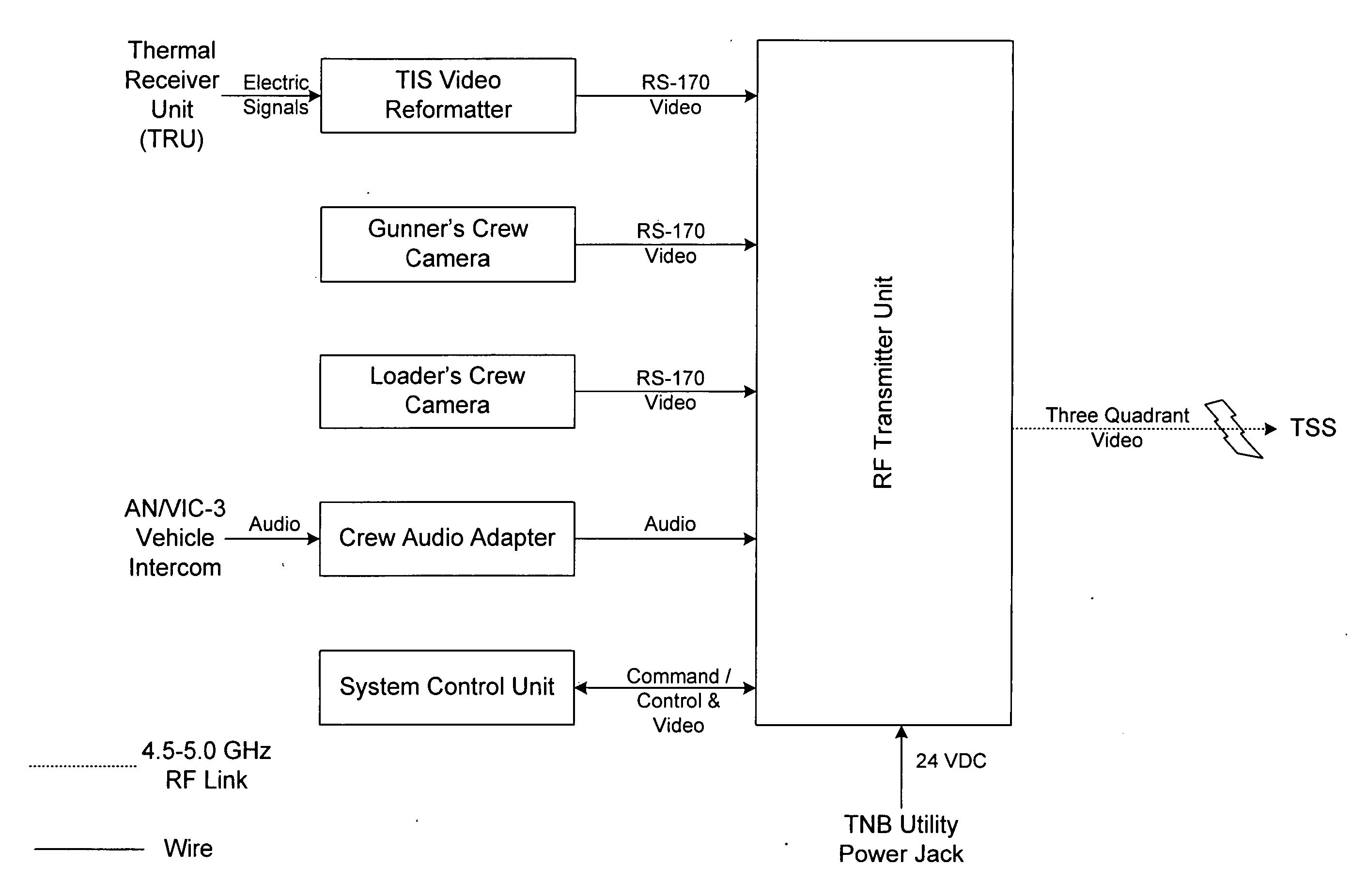
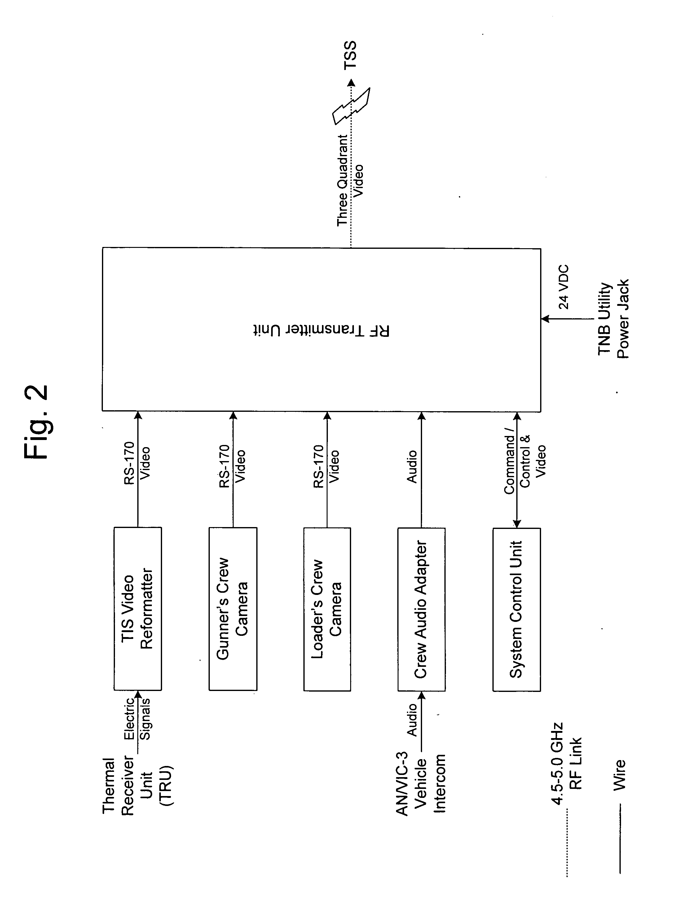
[0021] As shown in FIG. 2, the VRFS encompasses all of the componentry installed onto the host vehicle. A system has been designed and developed for the US Army M1A1 Abrams tank. Feasibility studies of the M2A2 Bradley Fighting Vehicle indicate a similarly designed system would be compatible. The VRFS is comprised of the RF Transmitter Unit (TU), Transmitter cable, two low-light cameras, Thermal Imaging System (TIS) Video Reformatter (VR), the System Control Unit (SCU), Intercom adapter, and a two-piece cable assembly. The two cameras, which use illuminating Light Emitting Diodes (LEDs) to improve its performance under very low-light conditio...


PUM


Abstract

The present invention provides a multi-split screen image with audio feed to document the training engagement. The multi video image combines an over-watch thermal image, the Loader's actions, the Gunner's actions, and the imagery from the vehicle's thermal imaging system. The audio track documents the communication within the vehicle and between the vehicle and the control tower. Further, the present invention provides a tower control module that also provides surveillance video over the firing range. Until the present invention no other gunnery-training device transmitted and displayed its imagery and audio in this manner.

Description

GOVERNMENT INTEREST [0001] The invention described herein may be manufactured, used, sold, imported, and / or licensed by or for the Government of the United States of America. FIELD OF INTEREST [0002] The invention relates to providing accurate records of a weapon system training crew's actions. More particularly, it relates to integrating vehicle and tower mounted imaging sensors, which act as performance evaluators to accurately and precisely grade an military field operation. BACKGROUND OF THE INVENTION [0003] The crewmembers of a weapon system, such as an US Army M1A1 Abrams Main Battle tank, must demonstrate their target acquisition and engagement skills during periodic live-fire gunnery training exercises. A typical Army gunnery training range is 1-3 kilometers in length by 500 meters wide. At the beginning of the range is a range control / observation tower. There are one or more roads, or firing lanes, on the range with one or more Battle Positions from where the vehicles engag...

Claims


Application Information

Patent Timeline
IPC IPC(8): F41A33/00
CPCF41A33/00F41G3/26G09B9/003
Inventor RAMBOYONG, LENARD V.ZINSER, PHILIP S.BACHELDER, PAUL W.THOMAS, CHARLES S.ROBERTS, MARK A.DUNCAN, EDWIN L.CLARK, LAWRENCE D.
Owner DEPT OF THE ARMY
Why Eureka
Try Eureka