
Corrugated plastic pipe with fastening portion

a corrugated plastic pipe and fastening technology, which is applied in the direction of pipe joints, adjustment joints, electrical equipment, etc., can solve the problems of reducing the cross-section of the end opening region affecting the quality of the corrugated pipe, and requiring comparatively large labor costs for the installation of the fittings on the corrugated pipe and further to the switch gear cabinet. , to achieve the effect of reducing the multiplicity of parts, reducing manufacturing

Inactive Publication Date: 2005-03-01
FRANKISCHE ROHRWERKE GEBRR KIRCHNER
View PDF22 Cites 20 Cited by
  • Summary
  • Abstract
  • Description
  • Claims
  • Application Information

AI Technical Summary

Benefits of technology

It is an object of the present invention to provide a new installation technology for corrugated plastic pipes. It is a further object according to the invention to provide more economical connections of corrugated pipes to switch gear cabinets, machine portions, or the like. It is further an object to reduce the manufacturing demands and the manufacturing costs as well as the installation demands as much as possible. Furthermore, it is an object of the invention to reduce the multiplicity of parts for the fastening of corrugated pipes.
It should be noted with respect to the abutment portion that it should be able to develop a large resistance and especially the largest possible resistance relative to the force, in order to function as a counter support without disadvantageous deformation.
It can further be an advantage to provide the corrugated plastic pipe in accordance with the invention with a longitudinal slit at least in those regions in which the corrugated pipe section is provided. Cable protection conduits could be fastened, for example, in the engine compartment of a motor vehicle through the screw connection, while the cables themselves are nevertheless accessible through longitudinal slits present for installation or maintenance purposes or the like.
Although it is possible to achieve with the molding of the threaded portion with a smaller outer diameter already a material concentration in the region of the threaded portion, an additional material concentration can be achieved by slowing down the corrugation or the speed of the circulating molding dies, so that the wall thickness in the region of the threaded portion is advantageously large to mechanically stabilize the corrugated pipe in the region of the threaded portion. It can also be attempted to otherwise achieve a material concentration in the region of the threaded portion.

Problems solved by technology

Such fittings are manufactured by way of injection molding at comparatively high cost, and the installation of the fittings on a corrugated pipe and further to a switch gear cabinet poses comparatively large labor demands.
Furthermore, this connection technology requires space, and manufacturing tolerances lead to a loss in cross-section with respect to the end opening region of the corrugated pipe.
Also, when such connections are to be manufactured liquid or gas tight, this results in much increased manufacturing and installation costs.

Method used


Image

  • Corrugated plastic pipe with fastening portion
  • Corrugated plastic pipe with fastening portion
  • Corrugated plastic pipe with fastening portion

Examples


Embodiment Construction

Equal or at least functionally equal components are referred to by the same reference numeral throughout the drawings.

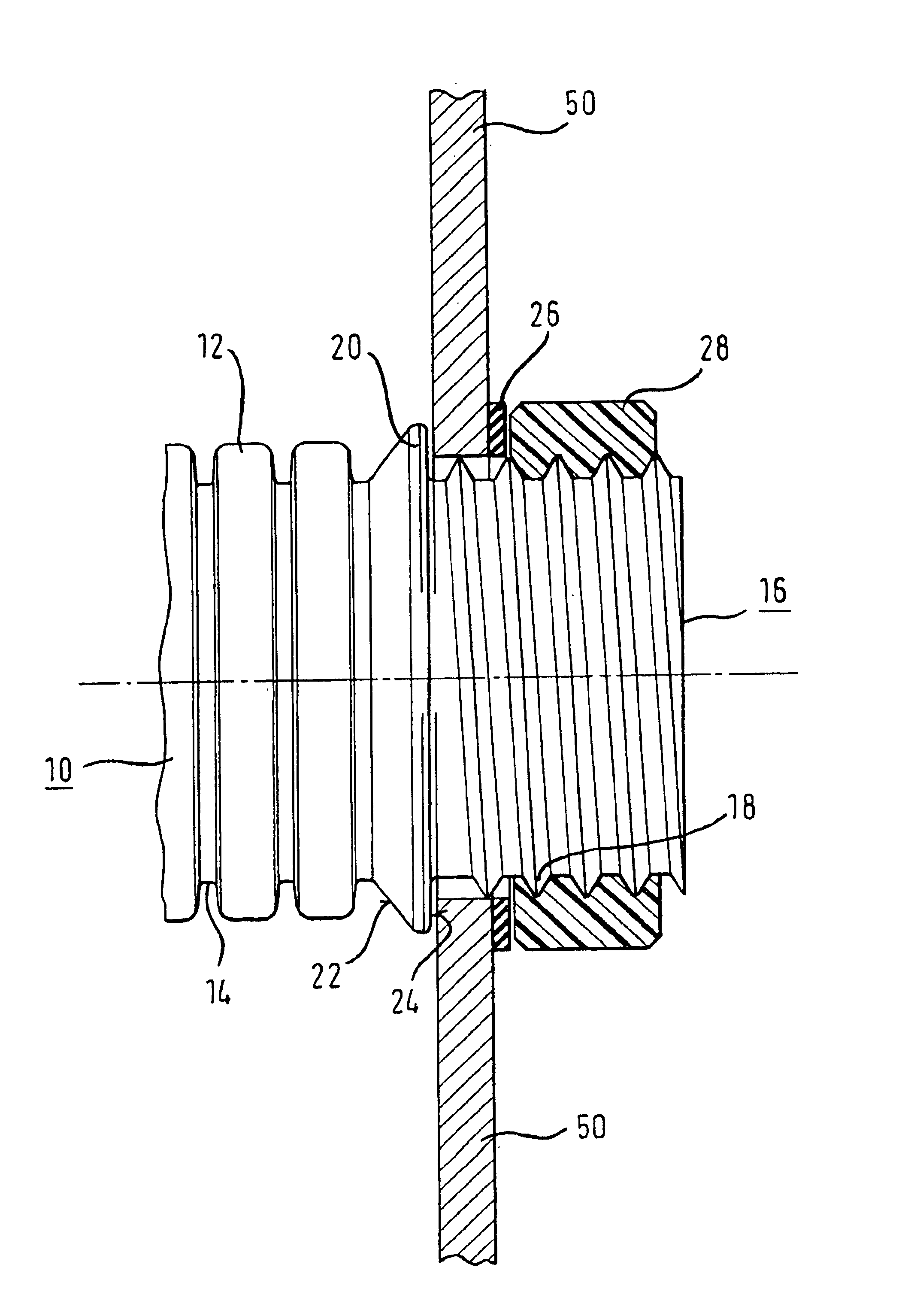
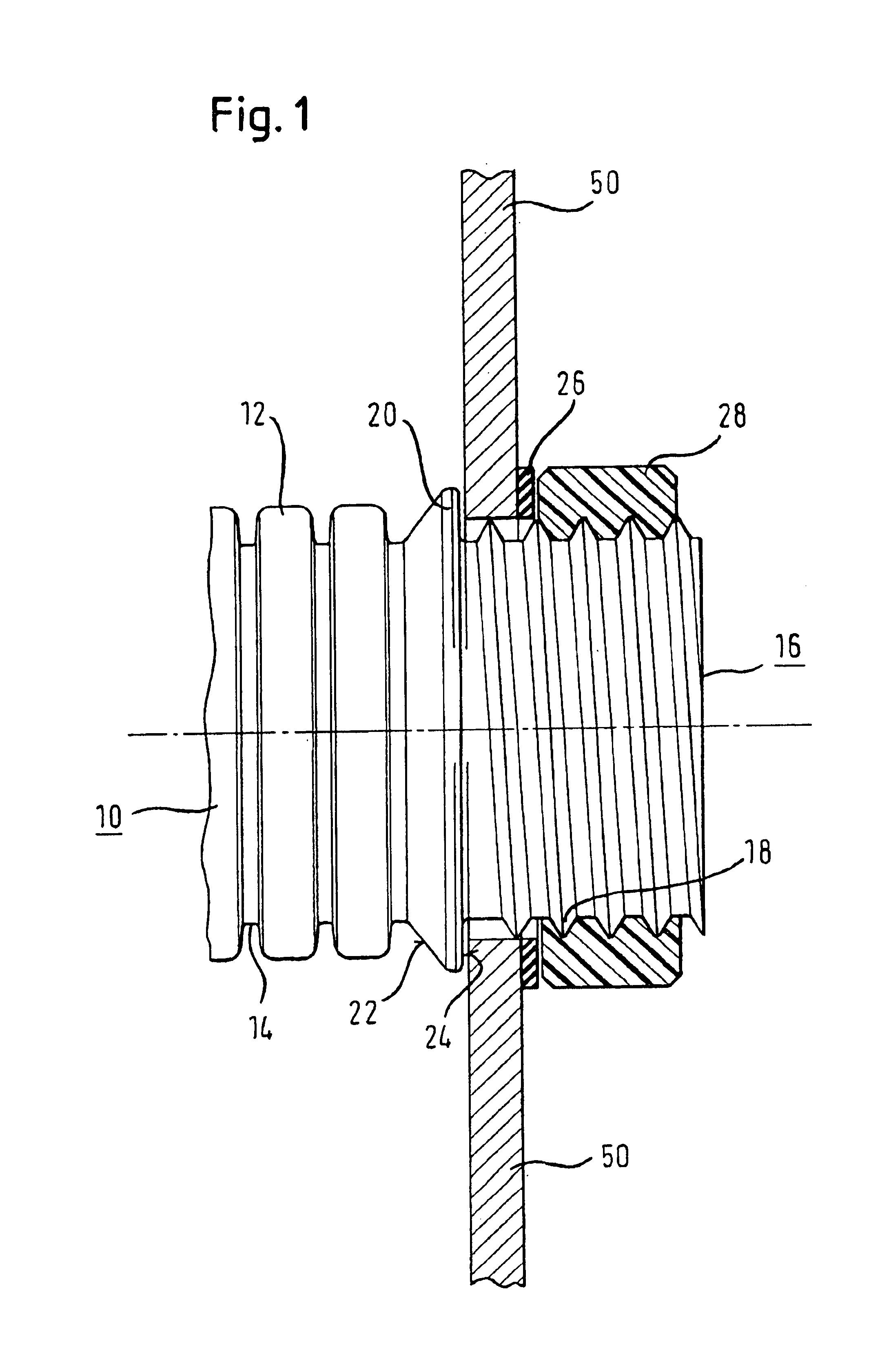
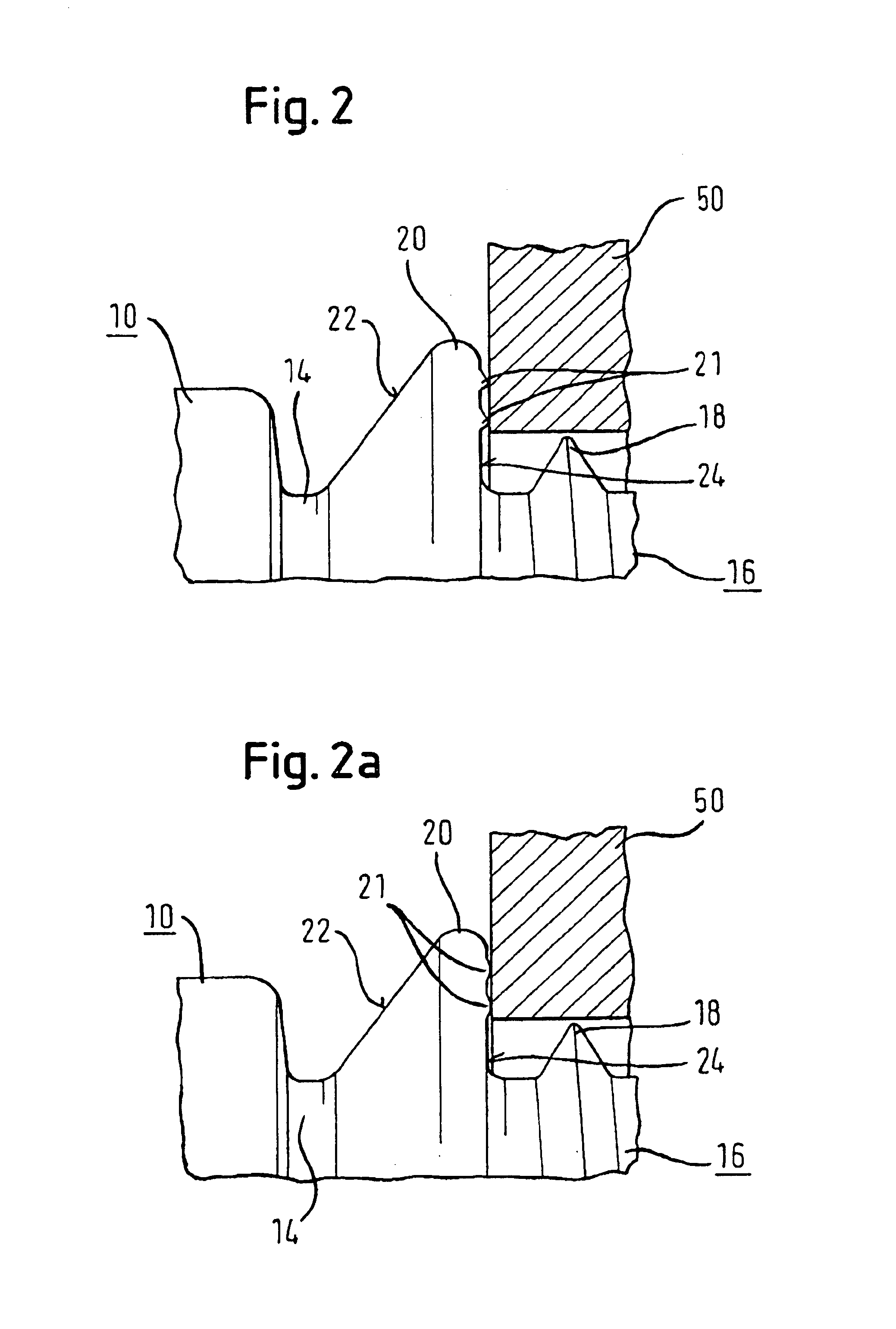
FIG. 1 shows a housing, a machine component or the like, for instance also a switch gear cabinet, which is represented by the wall portions 50 illustrated in cross-section. A corrugated pipe 10 with features according to the invention is guided through an opening in the wall portion 50. This corrugated plastic pipe 10 has, as is conventional, corrugation peaks 12 and corrugation valleys 14. One corrugation peak 20 is formed as an abutment, the flat surface 24 of which abuts the edges of the opening in the wall 50 on one side of the wall 50. The surface 24 serves as a counter support for the mechanical load, which occurs upon fastening of the pipe 10 to the wall 50.

The abutment portion 20 has a beveled or conically tapered shape 22 which serves to provide the abutment portion 20 with the required stiffness and distortion resistance which exceeds the mechanical strengt...


PUM


Abstract

A corrugated plastic pipe with an integral fastening section, whereby the corrugated plastic pipe can be fastened to any object by way of the fastening section.

Description

FIELD OF THE INVENTIONThe present invention relates to corrugated plastic pipes and processes for the manufacture of a corrugated plastic pipes. In particular, the invention relates to the fastening of corrugated pipes, for example, to or in household appliances, vehicles, machinery and the like.BACKGROUND ARTAccording to the prior art, electrical conduits or liquids, potentially also gasses, are guided into or back out of apparatus, switch gear cabinets, apparatus components or the like.In order to protect electrical cables from damage, they are guided in cable protection conduits, in general corrugated plastic pipes, for example, into switch gear cabinets. In order to abut the corrugated pipes to the corresponding cupboards and to fasten them thereto, whereby the cable must also not be damaged in the transition regions, fastening elements are used in the prior art which are generally referred to as connection fittings or fittings.Such fittings are manufactured by way of injection ...

Claims


Application Information

Patent Timeline
IPC IPC(8): F16L5/02F16L5/06
CPCF16L5/06H02G3/0691Y10S285/903
Inventor KRAUSS, MANFREDSCHROTER, SOREN
Owner FRANKISCHE ROHRWERKE GEBRR KIRCHNER
Learn More