Galvanic corrosion protective piping connection

a corrosion protection and piping technology, applied in the direction of pipe elements, sleeves/socket joints, mechanical equipment, etc., can solve the problems of compromising the piping, limited effect of providing a leak-free seal, and galvanic reaction, so as to prevent galvanic corrosion of the established connection

Inactive Publication Date: 2010-08-12
J & M MANUFACTURING CO INC
View PDF17 Cites 2 Cited by
  • Summary
  • Abstract
  • Description
  • Claims
  • Application Information

AI Technical Summary

Benefits of technology

[0009]It is therefore an objective of an aspect of the present invention to provide a mechanical connection that will allow for connection of differing materials to prevent galvanic corrosion of the established connection.

Problems solved by technology

These materials, however, can cause problems, especially when the materials themselves are mixed.
When different stainless materials are mixed together (as dictated by the needs of the piping system), the differing materials cause a galvanic reaction, compromising the piping over time.
Conventional techniques used for establishing pipe connections include various crimping technologies that exert tremendous force upon the ends of piping but have a limited effect on providing a leak-free seal.
Although well intentioned, the conventional techniques used for creation of piping connections have significant drawbacks.
First and foremost, these conventional techniques do not allow account for galvanic reactions that are created when different metallic materials are used in a piping connection.
These galvanic reactions lead to failure of the piping system over time.
Another significant drawback includes inappropriate crimp of the piping system that in turn allows materials to escape from the system.
Large and expensive crimping tools must be used to establish these connections which is a significant drawback during fabrication of the piping system.
To overcome these significant drawbacks, other conventional techniques include soldering and\or welding of pipe sections together that in turn causes increased costs for fabrication of the system.

Method used


Image

  • Galvanic corrosion protective piping connection
  • Galvanic corrosion protective piping connection
  • Galvanic corrosion protective piping connection

Examples


Embodiment Construction

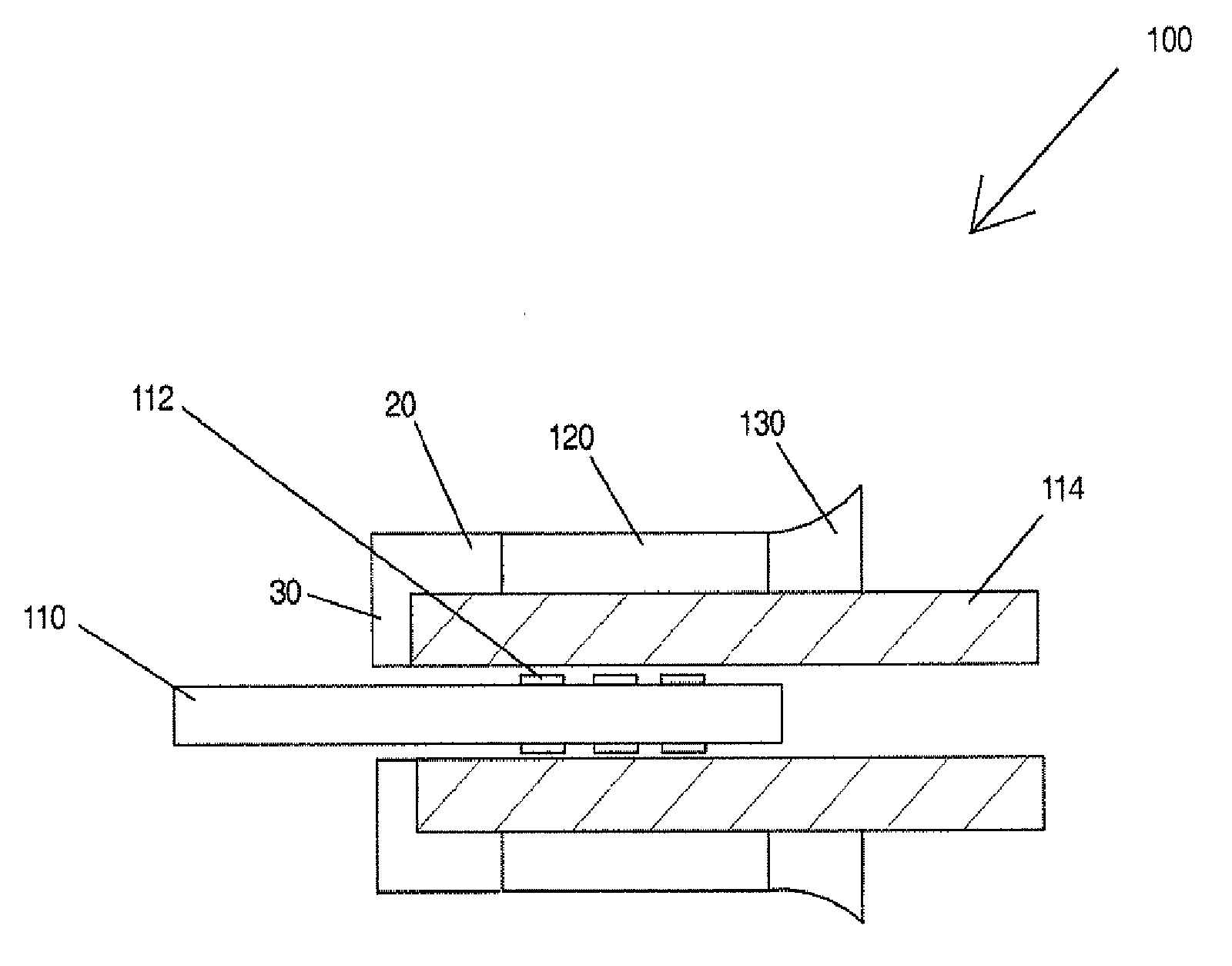
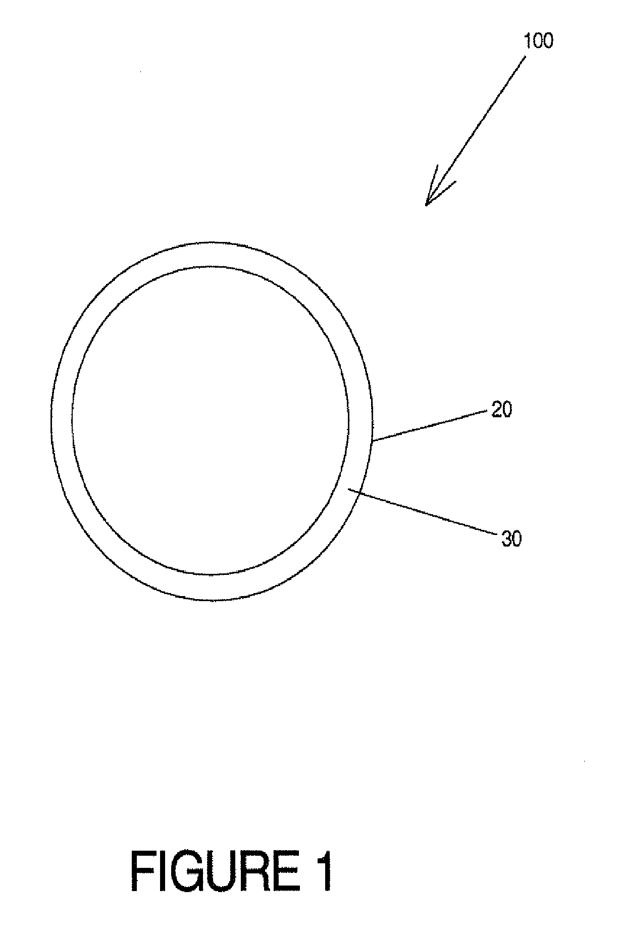
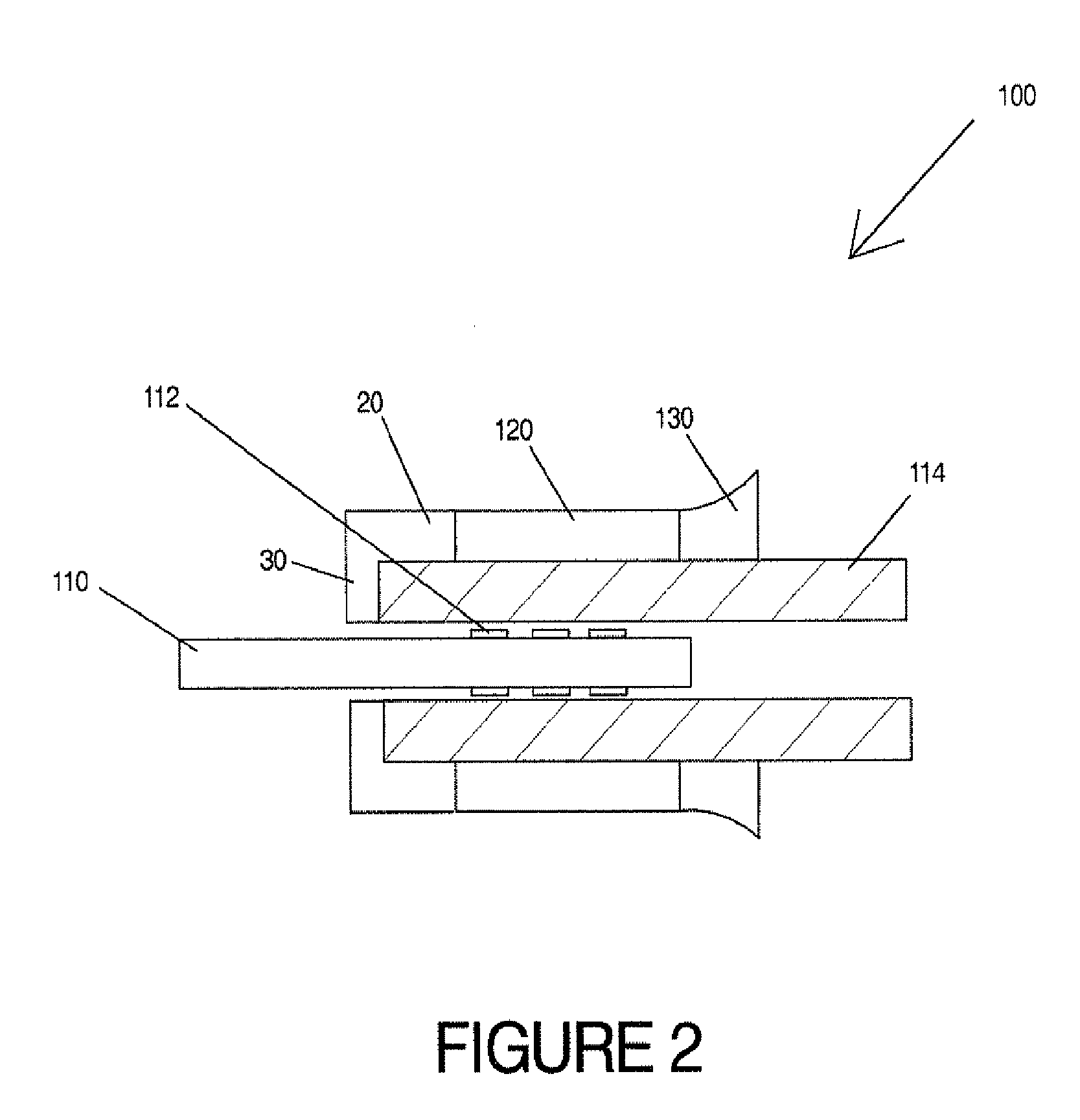
[0024]Referring to FIG. 1, a front view of a piping connector 100 is illustrated. In this front view a galvanic shield 20 is provided. The galvanic shield 20 prevents galvanic interaction between materials of differing components thus preventing corrosion from occurring. Unchecked corrosion, may lead to degradation of the piping system and is an undesirable feature of conventional piping systems. In the present invention, however, the galvanic shield 20 prevents contact between differing metallic parts of a piping system and therefore prevents corrosion from occurring. The galvanic shield 20 is provided on an end of a pipe such that a spool piece may be inserted into the pipe and the pipe crimped to establish a connection between the pipe and the spool piece. The galvanic shield 20 may be made of any material to prevent galvanic reaction from occurring between the differing metallic components of the connection. In the illustrated embodiment provided, the material is a high temperat...


PUM


Abstract

A piping connector having a crimp section configured to snugly fit around an external diameter of a pipe, the crimp section having one of a flared and an unflared edge, and a galvanic shield connected to the crimp section, wherein the galvanic shield covers a exterior diameter of a pipe end to be connected and frontal face of the pipe end, wherein a joint between the crimp section and the galvanic shield is one of a chemical connection and a mechanical connection.

Description

FIELD OF THE INVENTION[0001]The present invention relates to piping connections. More specifically, the present invention provides a piping connection that provides a secure connection between the individual piping sections to be joined, while protecting against galvanic corrosion between different materials used in the pipe connection.BACKGROUND INFORMATION[0002]Connection of piping is an important function in creating a piping system. Piping systems may be used for mass transport for materials, such as fluids and gases. These piping systems may be manufactured of differing materials such as, plastic, iron, copper or other similar materials. These materials, however, can cause problems, especially when the materials themselves are mixed. When different stainless materials are mixed together (as dictated by the needs of the piping system), the differing materials cause a galvanic reaction, compromising the piping over time.[0003]Conventional techniques used for establishing pipe con...

Claims


Application Information

Patent Timeline
Patent Type & Authority Applications(United States)
IPC IPC(8): F16L21/00
CPCF16L13/141
Inventor LIN, MICHAEL
Owner J & M MANUFACTURING CO INC
Why Eureka
Try Eureka