Method and apparatus for connecting piping

a technology of connecting piping and piping materials, applied in the direction of hose connection, pipe coupling, coupling, etc., can solve the problems of limited effect on providing leak-free seal, difficult connection of piping materials, and significant drawbacks of conventional techniques used for creating piping connections, etc., to achieve minimize galvanic corrosion, simple connection, and simple connection

Active Publication Date: 2014-04-15
J & M MANUFACTURING CO INC
View PDF19 Cites 0 Cited by
  • Summary
  • Abstract
  • Description
  • Claims
  • Application Information

AI Technical Summary

Benefits of technology

[0012]It is also an objective of an aspect of the present invention to provide a mechanical connection that will connect different sections of the piping system in an economical manner.
[0014]Is a still further objective of an aspect of the present invention to provide a simple connection for use in a piping system that may be used by installers without the need for special training. It is also an objective of an aspect of the invention to provide a simple connection that may be used with pipe or tubing to create piping / tubing systems. It is also an objective of the invention to provide an arrangement and method of connecting pipe or tubing such that galvanic corrosion is minimized and / or eliminated.

Problems solved by technology

Connection of piping materials can prove to be difficult.
Conventional techniques include various crimping technologies that exert tremendous force upon the ends of piping but have a limited effect on providing a leak-free seal.
Although well intentioned, conventional techniques used for creation of piping connections have significant drawbacks.
Such significant drawbacks can include inaccurate crimping of the piping system, thereby allowing fluids, such as liquids and gases, to escape from the piping system.
An additional significant drawback includes the use of highly specialized tools to prevent significant over crimping of the piping system.
The specialized tools can be extremely expensive and cumbersome and cannot be used in tight quarters or in areas of limited accessibility.
While welding of the individual piping sections is an acceptable technique for providing a proper mechanical connection, the costs associated with welding of the piping system can be extremely high.
Thus, when a significant number of welds is to occur in a piping system, such as in a new home placement, or in an industrial setting, the cost of piping insulation can skyrocket leaving the owner of the piping system with little alternative but to pay for expensive mechanical connections.

Method used


Image

  • Method and apparatus for connecting piping
  • Method and apparatus for connecting piping
  • Method and apparatus for connecting piping

Examples


Embodiment Construction

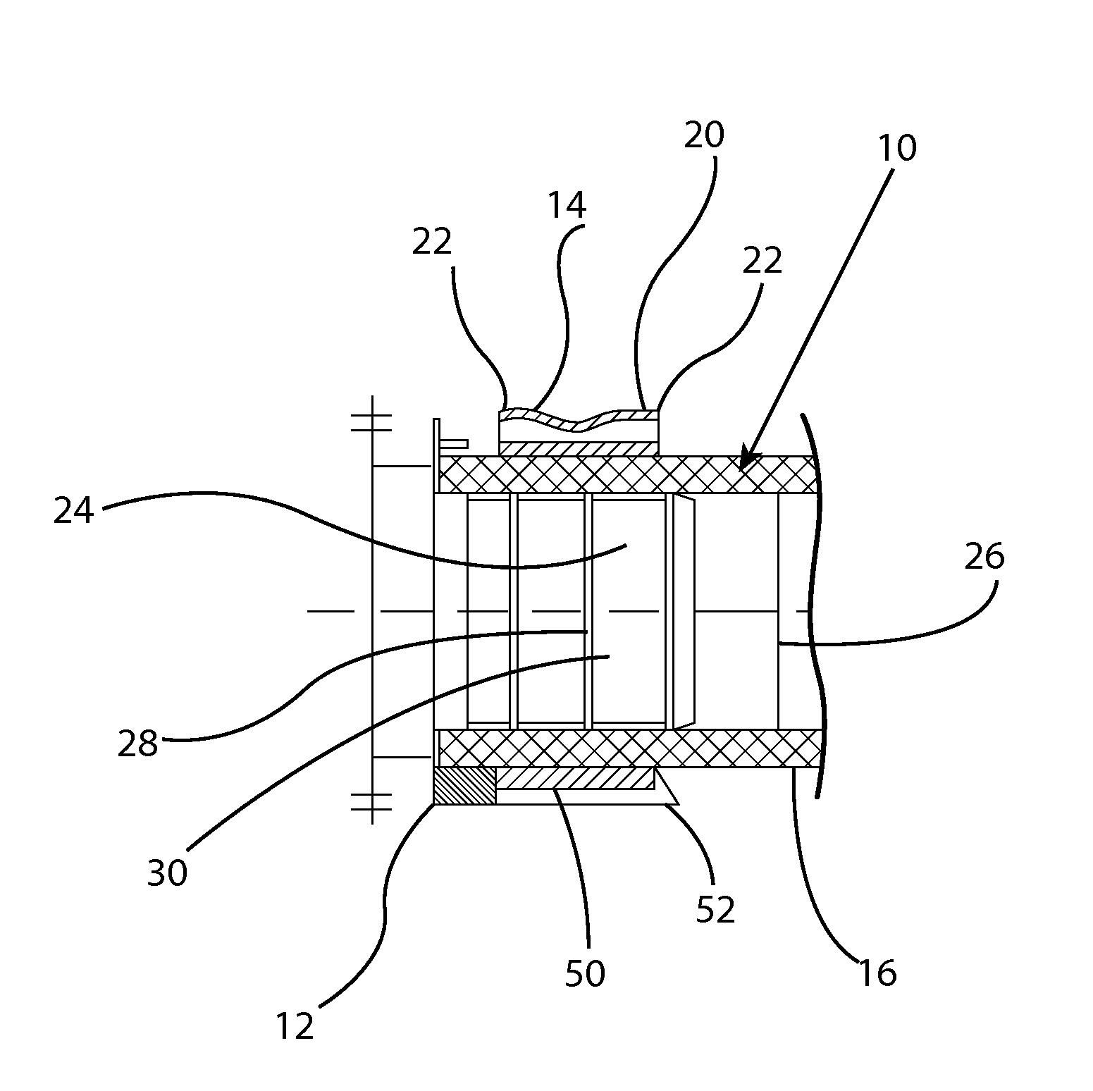
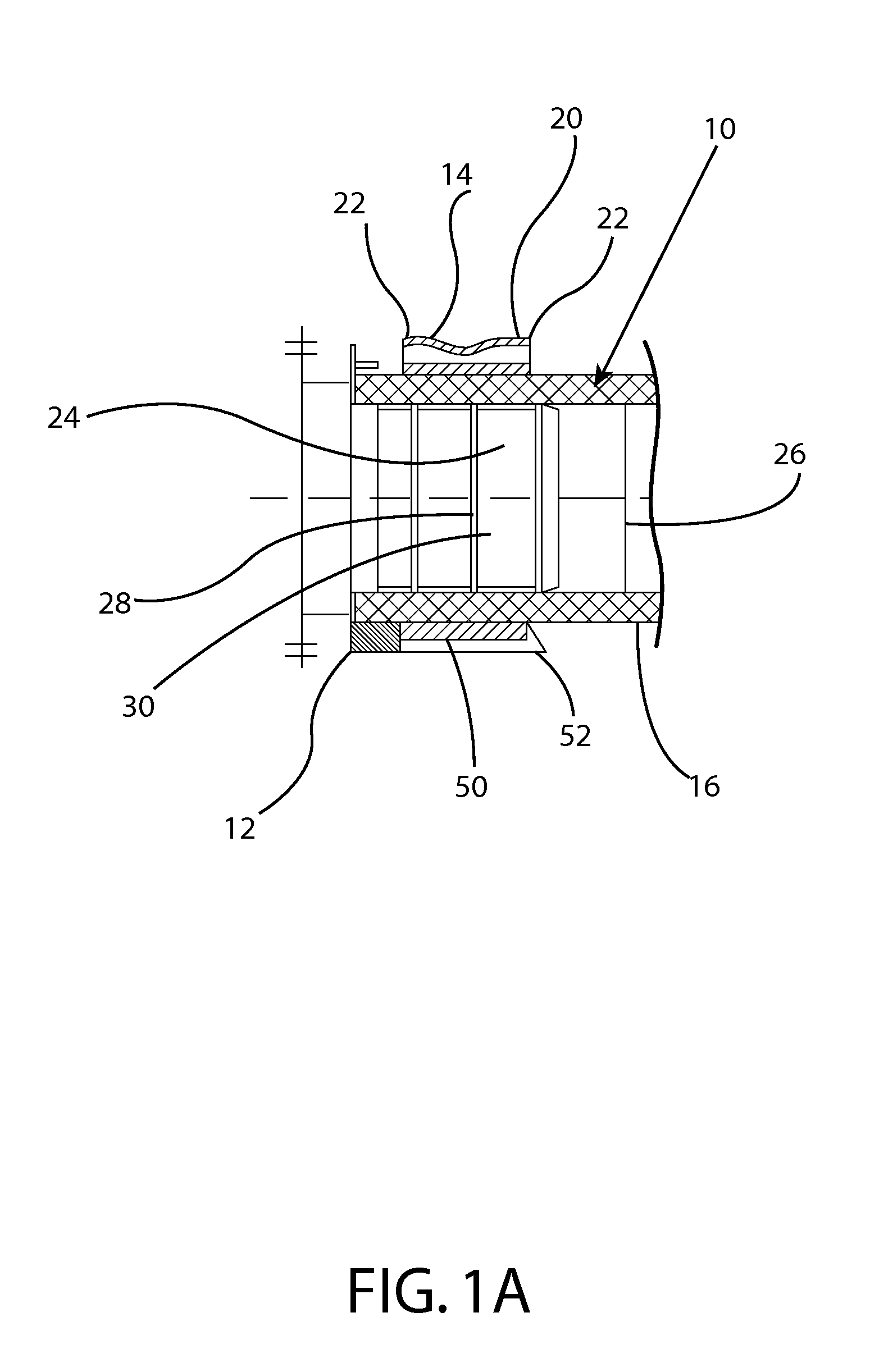
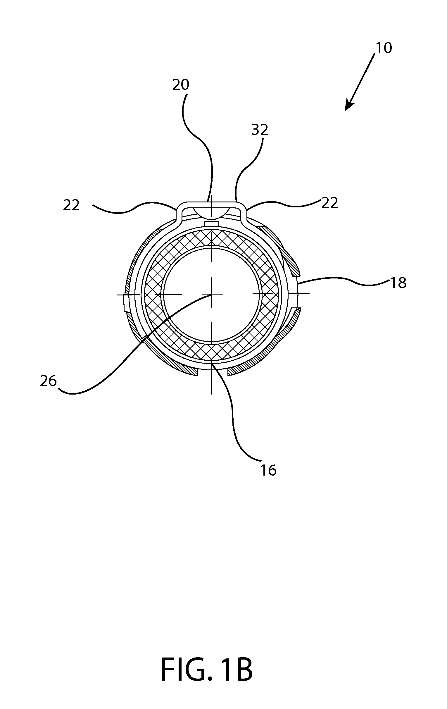
[0039]Referring to FIGS. 1a, 1b and 1c, a piping connector 10 is provided. The piping connector 10 is used to connect pipes together to create a piping systems through the attaching the pipe to an insert. In the exemplary embodiment, two main elements of the piping connector 10 are provided, namely a shield 12 and an ring 14. The ring may be an Oetiker type clamp, in an exemplary embodiment. Referring to FIG. 1a, a side view of the piping connector 10 is illustrated installed on a pipe 16. FIG. 1b illustrates the piping connector 10 of FIG. 1a from a front view without ring 14 compression (an uninstalled state). FIG. 1c illustrates the piping connector 10 front view with the ring 14 in a compressed state. As provided in FIG. 1a, the shield 12 installs upon the ring 14 allowing portions of the ring 14 to penetrate portions of the shield 12. The penetrations 18 provided in the shield 12 are sufficiently sized to allow portions of the ring 14 such as a clamp closing portion 20 to protr...


PUM

PropertyMeasurementUnit
external diameteraaaaaaaaaa
internal diameteraaaaaaaaaa
forceaaaaaaaaaa

Abstract

A piping connector is provided having a ring configured to install around an external diameter of a pipe, the ring having at least one clamp closing portion that has an open uncrimped position and a closed crimped position, a piping shield connected to the ring, the piping shield having at least one penetration to accept the at least one clamp closing portion, wherein the piping shield covers an abutment end of the pipe to be connected, wherein a joint between the ring and the piping shield forms a connection.

Description

CROSS-REFERENCE TO RELATED APPLICATIONS[0001]The following application claims priority to Chinese Patent Application 200720095006.7, filed Jan. 19, 2007, which is included by reference in its entirety.FIELD OF THE INVENTION[0002]The present invention relates to piping connections. More specifically, the present invention provides a piping connection that provides a secure connection between the individual piping sections to be joined.BACKGROUND INFORMATION[0003]Connection of pipe is an important function in creating a piping system. Piping systems may be used, for example, for transport of materials, such as fluids and gases. These piping systems may be manufactured of differing materials such as, plastic, iron, copper or other similar materials.[0004]Connection of piping materials can prove to be difficult. Conventional techniques include various crimping technologies that exert tremendous force upon the ends of piping but have a limited effect on providing a leak-free seal. Such c...

Claims


Application Information

Patent Timeline
Patent Type & Authority Patents(United States)
IPC IPC(8): F16L33/00
CPCF16L19/14F16L2201/10F16L33/025F16L33/2071F16L13/141Y10T29/49954Y10T29/49908
Inventor LIN, MICHAELZHANG, LEI
Owner J & M MANUFACTURING CO INC
Why Eureka
Try Eureka