
Method and apparatus for improved stiffness in the linkage assembly of a flexible arm

a flexible arm and linkage technology, applied in the direction of couplings, applications, surgical instrument supports, etc., can solve the problems of reducing the frictional force needed for stiffness, slipping of links, and inability to reuse, and achieve the effect of small diameter differen

Inactive Publication Date: 2005-03-01
TERUMO CARDIOVASCULAR SYST CORP
View PDF6 Cites 34 Cited by
  • Summary
  • Abstract
  • Description
  • Claims
  • Application Information

AI Technical Summary

Benefits of technology

The invention address the needs discussed in the background. The invention increases the stiffness of flexible arm linkage assemblies, by increasing the friction between link contacts when in a locked configuration.
A flexible arm including the invention provides an increased range of motion and better stabilization of surgical instruments.
Metallic links have a significant advantage when used in a surgery, they can be sterilized and reused many times. Using metal linkage assemblies reduces the waste products and lowers the costs associated with the use of flexible arms.
The inventors further experimentally proved that they could make an even better joint using contact materials of stainless steel and titanium for the respective contact surfaces based upon the optimized interface geometry. The joint formed from the stainless steel contacting titanium beads had greatly improved stiffness over anything the inventors know of.

Problems solved by technology

Plastic links have a significant problem when used in a surgical theatre, they often cannot be reused due to difficulties in cleaning them.
By having the low coefficient of friction, such links slipped easily, far below the point of usefulness.
First, maximizing the stainless steel contact area actually reduces the frictional force needed for stiffness.
The disclosure from the Summary was appropriate for a plastic link component, but failed to account for the physical characteristics of stainless steel as well as alloys of iron and titanium, which do not deflect anywhere near as much as plastics.
There is an additional problem with highly textured metallic contact surfaces.
They would be difficult to clean, posing a health risk if reused in a surgical setting.

Method used


Image

  • Method and apparatus for improved stiffness in the linkage assembly of a flexible arm
  • Method and apparatus for improved stiffness in the linkage assembly of a flexible arm
  • Method and apparatus for improved stiffness in the linkage assembly of a flexible arm

Examples


Embodiment Construction

Various embodiments built in accord with the invention will be discussed. The invention increases the stiffness of flexible arm linkage assemblies, by increasing the friction between link contacts, when in a locked configuration operating similarly to existing plastic based linkage assemblies.

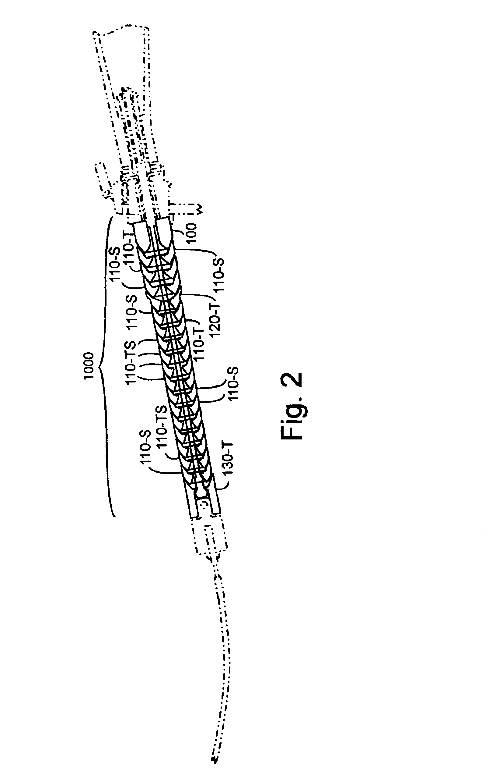
The invention includes a flexible arm linkage assembly provided with a tensioning cable. The linkage assembly includes a first link with a first contact surface composed of a first contact material, and a second link with a second contact surface composed of a second, differing contact material. A high friction coupling between the first link and the second link is created by the first contact surface contacting the second contact surface when induced by the tensioning cable.

Each of the contact materials is primarily composed of a respective metallic compound, or compounds, providing a higher coefficient of friction between the two contacting surfaces than would result from both contacting surf...


PUM


Abstract

The invention includes linkage assemblies comprising coupled links with metallic contact surfaces with improved stiffness. The inventors found significant mechanical problems with all previous descriptions of metallic contact links sufficient to preclude their commercial use. These metallic contact links are a significant improvement over existing plastic ball and metal joint, or all plastic beads as found in the prior art. The invention includes methods providing these links and high friction couplings between them, as well as the linkage assemblies and flexible arms resulting from these processes.

Description

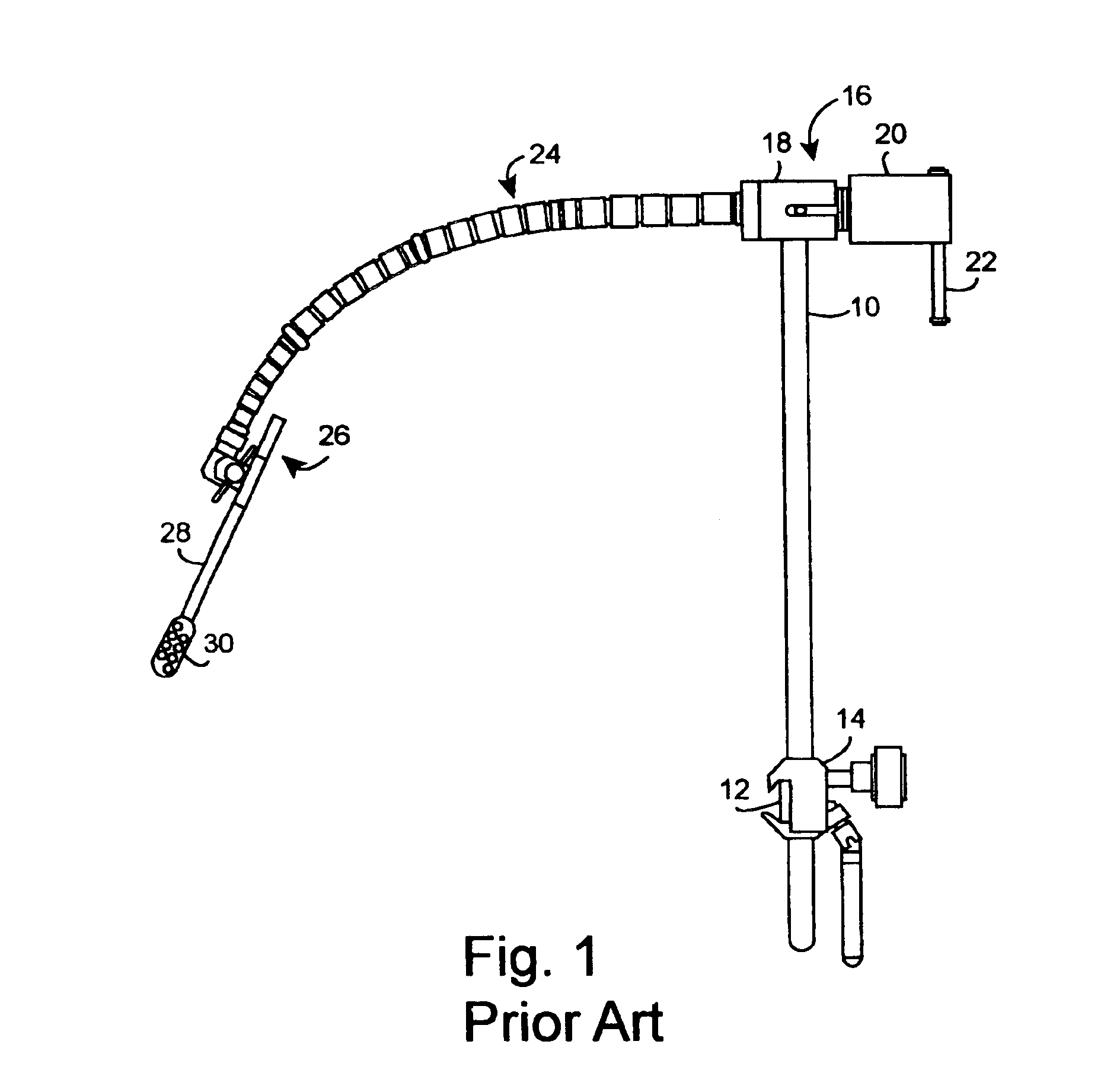
TECHNICAL FIELDThe present invention relates to articulating load bearing flexible arms, particularly suited for use as surgical tissue stabilizers, and more particularly to increasing the stiffness of such an articulating column when in the locked configuration.BACKGROUND ARTFlexible arms or, as they are often called, articulable columns, have many uses. For example, they are often used for positioning tools, article supports, or for locking measuring apparatus. In surgery, it is common practice to mount them as adjustable supporting brackets on a side rail of an operating table to support retractors, endoscopes and other surgical devices.U.S. Pat. No. 4,949,927 discloses an articulable column and, more particularly, describes prior art columns of the ball and socket type which are flexible in their normal state and which, by application of tension from a central cable, become rigid.Recent developments in heart surgery require stronger and more rigid adjustable brackets. In particu...

Claims


Application Information

Patent Timeline
Patent Type & Authority Patents(United States)
IPC IPC(8): F16C11/06A61B17/00A61B17/02A61B19/00A61KF16C11/10F16L9/22F16L11/18F16M11/14F16M11/40
CPCA61B17/02A61B19/26F16L11/18F16M11/14F16M11/40F16M13/02Y10T403/32311F16M2200/022A61B2019/268Y10T403/32032Y10T403/32041A61B90/50A61B2090/571A61B1/00149
Inventor IBRAHIM, TAMERGEYSTER, STEVEGLEESON, JAMESHAUBERT, THOMAS D.PRESCOTT, JAMES A.
Owner TERUMO CARDIOVASCULAR SYST CORP
Learn More