Field tapering in magnetic spheres and cylinders with distortion free access

a magnetic sphere and cylinder technology, applied in the field of permanent magnets, can solve problems such as distorting the interior field and not being technically feasibl

Inactive Publication Date: 2005-03-01
UNITED STATES OF AMERICA AS REPRESENTED BY THE THE
View PDF11 Cites 11 Cited by
  • Summary
  • Abstract
  • Description
  • Claims
  • Application Information

AI Technical Summary

Benefits of technology

A further aspect involves a method of making a permanent magnet having a cavity, comprising providing at least one first segment having a first magnetic field that has a single predetermined direction of magnetization and that has a uniform first remanence; providing at least one second segment having a second magnetic field that has a direction of magnetization (γ) that varies circumferentially along the segment according to the formula γ=(2)(θ) where θ is a polar angle from θ=0° to θ=360° and wherein the second magnetic field comprises a second remanence which increases in magnitude from θ=0° to θ=180° and decreases in magnitude from θ=180° to θ=360°; and combining the at least one first segment and the at least one second segment to form a permanent magnet.

Problems solved by technology

Ideally the change in direction of magnetization should be continuous but this is not technically feasible.
However, removal of magnetic material to provide an access port to the interior through the magnetic shell will distort the interior field especially in the vicinity of the port.

Method used


Image

  • Field tapering in magnetic spheres and cylinders with distortion free access
  • Field tapering in magnetic spheres and cylinders with distortion free access
  • Field tapering in magnetic spheres and cylinders with distortion free access

Examples


Embodiment Construction

One embodiment of the present invention concerns a permanent magnet that has both a cavity comprising a gradient magnetic field and a distortion free access port. In another embodiment of the invention, a permanent magnet may comprise a plurality of first and second segments that may be easily assembled together to provide the desired magnetic field parameters.

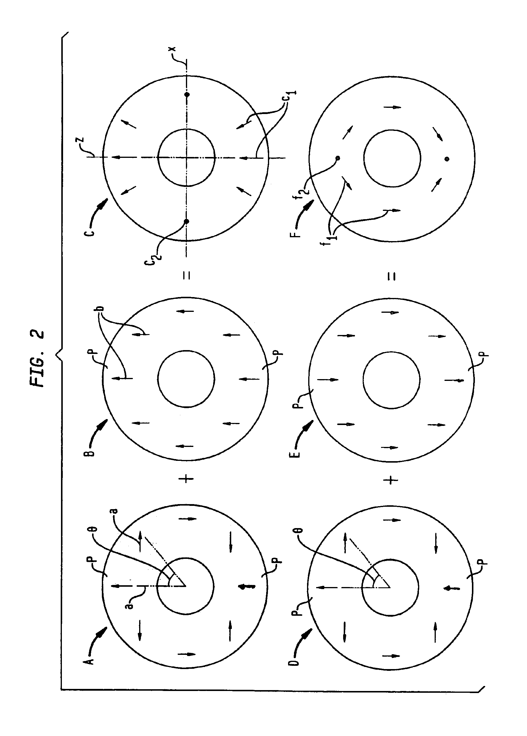
Referring to FIG. 2, and in accordance with an embodiment of the present invention, a combination of magnetic rings, each having a particular magnetization, may be combined to form a magnetic ring having a particular resultant magnetization, the particulars of which may be found by vector analysis. For example, a first magnetic ring A including a magnetization direction and magnitude represented by arrows a may be combined with a magnetic ring B including a magnetization represented by arrows b (of equal magnitude to those of arrows a and in tandem at poles p where θ=0° and θ=180°) to form a magnetic ring C that has a resultin...


PUM

PropertyMeasurementUnit
magnetic remanence Braaaaaaaaaa
magnetic fieldaaaaaaaaaa
remanence Braaaaaaaaaa

Abstract

A permanent magnet comprises a shell surrounding a cavity. The shell has a magnetic remanence Br(θ) configured such that a magnetic field taper extends through the cavity and wherein the shell includes a non-distortive access region that is substantially magnetic field.

Description

BACKGROUND OF THE INVENTION1. Field of the InventionThe present invention relates generally to permanent magnets and, more particularly, to high intensity permanent magnets having gradient fields and to methods of making such magnets.2. Related ArtPermanent magnets that are capable of producing high intensity magnetic fields and that have a compact structure are known and are used, e.g., in miniaturized electrical components including disk drives for laptop and palmtop computers. In particular, permanent magnet materials that are highly remanent and coercive, such as those of the rare earth type, are produced to make compact flux sources of extraordinary strength. Examples of high-intensity, compact permanent magnets, which may employ these materials, may be found in the following patents. U.S. Pat. No. 4,837,542, to Leupold, entitled “Hollow Substantially Hemispherical Permanent Magnet High Field Flux Source for Producing a Uniform High Field”; U.S. Pat. No. 4,839,059 to Leupold, e...

Claims


Application Information

Patent Timeline
Patent Type & Authority Patents(United States)
IPC IPC(8): H01F7/02
CPCH01F7/0278H01F7/0268
Inventor LEUPOLD, HERBERT A.
Owner UNITED STATES OF AMERICA AS REPRESENTED BY THE THE
Why Eureka
Try Eureka