Reflector antenna having low-dielectric support tube for sub-reflectors and feeds
- Summary
- Abstract
- Description
- Claims
- Application Information
AI Technical Summary
Benefits of technology
Problems solved by technology
Method used
Image

Examples
Embodiment Construction
The following description of the preferred embodiment(s) is merely exemplary in nature and is in no way intended to limit the invention, its application, or uses.
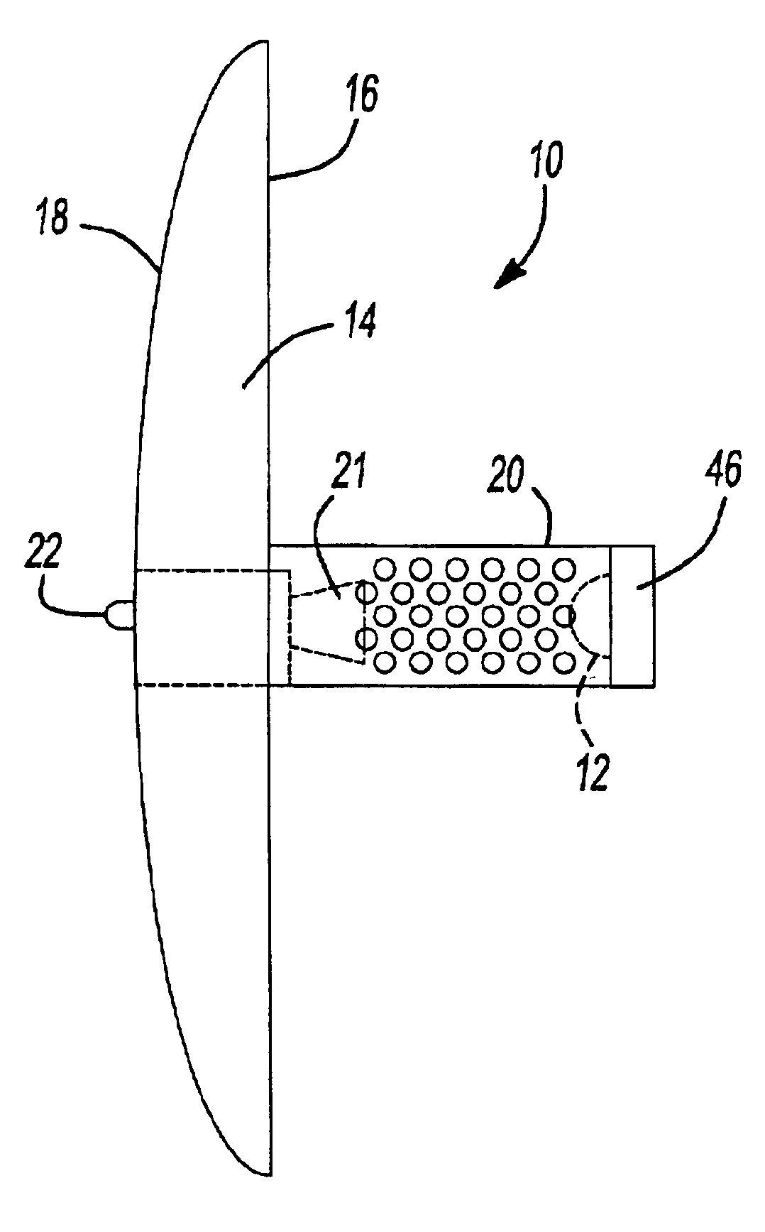
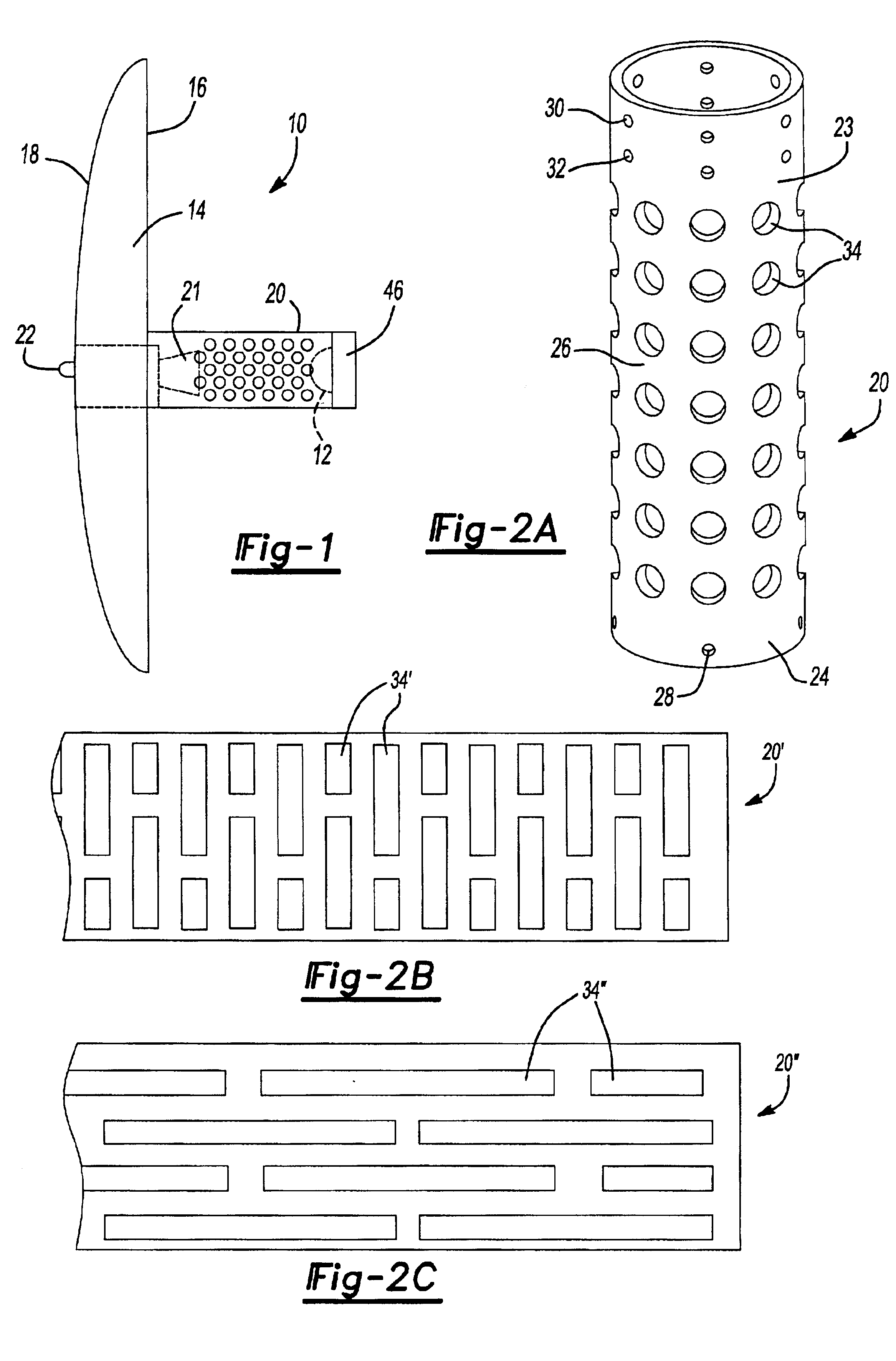
As seen in FIG. 1, an antenna 10 in accordance with a first preferred embodiment of the present invention is shown. The antenna 10 contains a hyperbolic sub-reflector 12 and a parabolic main reflector 14. The main reflector 14 has a first surface 16 and a second surface 18. The sub-reflector 12 is mounted to the first surface 16 by a perforated plastic support tube 20. Electromagnetic wave signals, such as RF signals, received by the first surface 16 are reflected by the sub-reflector 12 to a waveguide in the form of a feedhorn 21. Electromagnetic wave signals, such as RF signals, transmitted through the feedhorn 21 are reflected by the sub-reflector 12 to the first surface 16 and radiate from the first surface 16 into space. RF signals received by the antenna 10 are carried from the antenna 10 through a suitable conducting...
PUM
 Abstract
Description
Claims
Application Information