
Color display system

a color display and monitor technology, applied in the field of color monitors and displays, can solve the problems of inaccurate gamma function, inability to view the correct color of clothing, and inability to accurately match the color of clothing, etc., and achieve the effect of high color fidelity

Inactive Publication Date: 2005-03-01
HEWLETT PACKARD DEV CO LP
View PDF33 Cites 329 Cited by
  • Summary
  • Abstract
  • Description
  • Claims
  • Application Information

AI Technical Summary

Benefits of technology

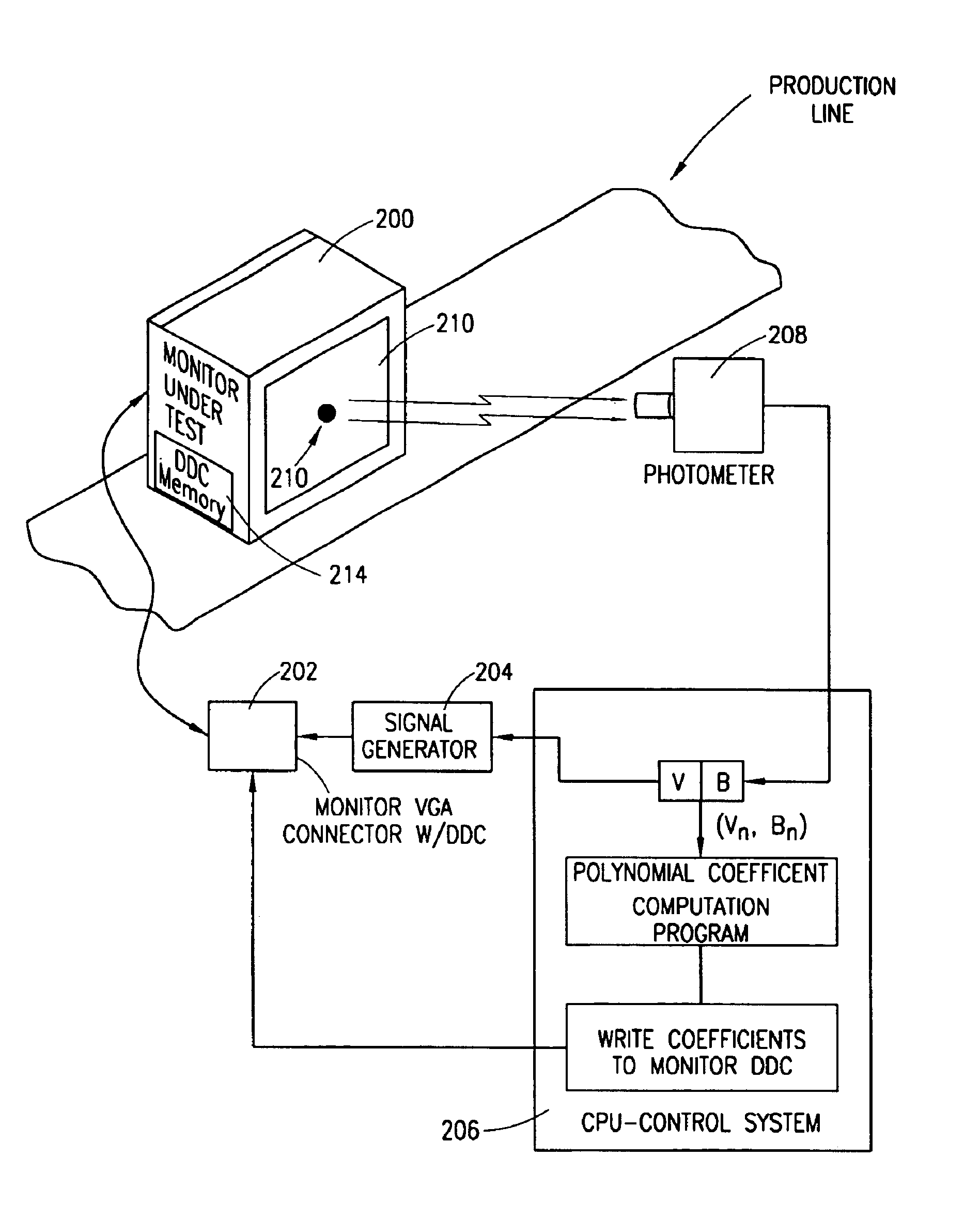
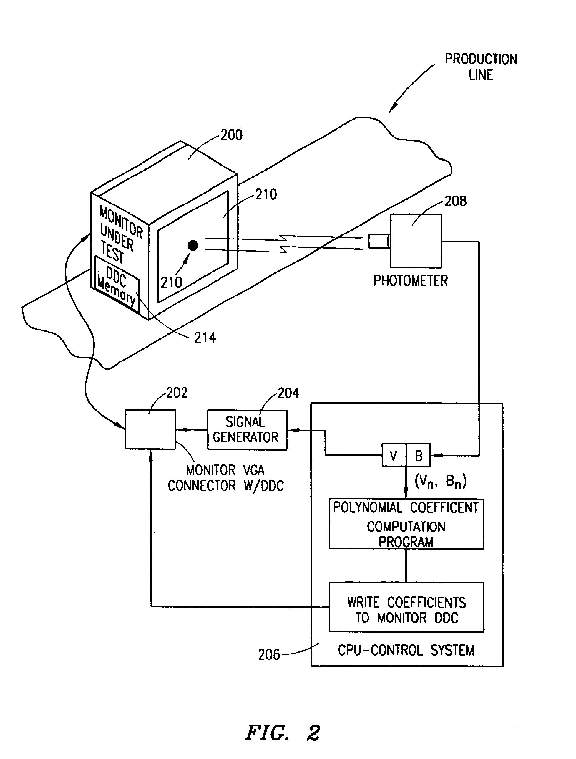
An exemplary embodiment of the present invention may comprise a photometer and video pattern generator that are interfaced to a computer system. The computer system may be equipped with a means to write to a non-volatile memory within a color display device. A color display device is tested by placing the photometer in front of the display device under test. The computer controls the pattern generator so as to drive the display with incremental input signals corresponding to an output display color. For each incremental input from the pattern generator, the photometer measures the actual brightness output of the color on the color display device and provides the measurement to the computer for storage in a memory device. This is done for each color; red, green and blue, from a maximum brightness to a minimum brightness. After recording all the input signal-to-brightness information for each color, the computer computes coefficients for a third order polynomial for each color channel that best represents the correlation between the incremental inputs and the resulting brightness measurements for each color. In effect, a transfer function is created describing the signal-input-to-brightness-output characteristics for each color. The transfer function can be a third order polynomial equation. The computed coefficients for the third order polynomial for each color (12 coefficients, 4 for each color red, green and blue) can then be provided to and stored in a non-volatile memory within the display device. The coefficients can then be utilized by display driver circuitry within a computer to which the tested display device is connected. The display driver can utilize the coefficients to help provide an accurate high color fidelity, standardized picture on the monitor.

Problems solved by technology

Via experimental observation, it has been determined that the gamma function, though the standard in the industry, is inaccurate.
At present, the gamma function will not necessarily allow the potential buyer to view the correct color of the clothing.
This is a significant problem in the area of standardizing the color in a color display device.

Method used


Image

  • Color display system
  • Color display system
  • Color display system

Examples


Embodiment Construction

An exemplary embodiment of the present invention prescribes a method for establishing a transfer function, and preferably, a third order polynomial that describes a relationship between an input to a color monitor and the resulting color brightness of the monitor for each color red, green and blue. In essence, a polynomial representation of the input-output characteristics of a color display device is established.

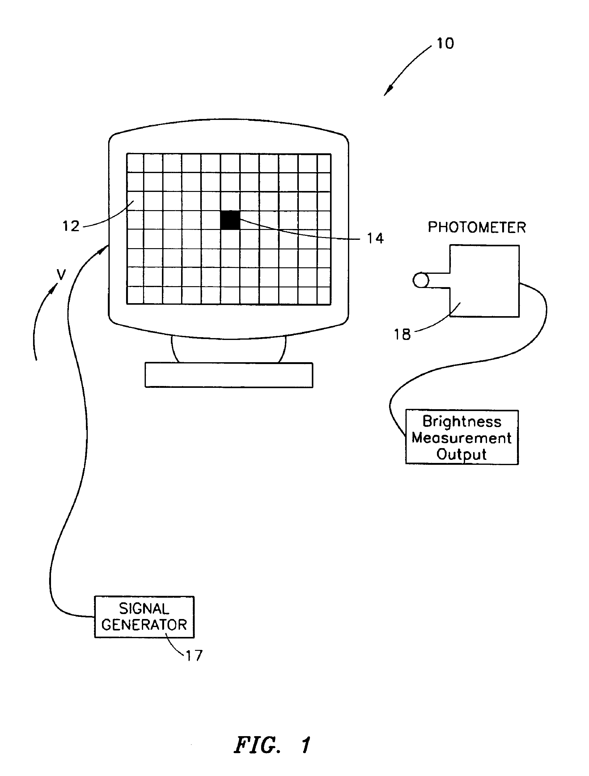
Referring to FIG. 1, a CRT 10 is depicted. It is noted that this method can be used for substantially any display device. Such display devices include, but are not limited to, color display devices, VGA flat panel NCDs or SPVs, LCD, reflective LCD, and FED display devices. Regardless, of the type of color display device 0, a video signal (or its equivalent) is inputted into the color display device (CDD) 10 and a pattern is outputted on the CDD's screen. A grid or plurality of pixels 12 make up the displayed pattern. A pixel is a picture element or an addressable element wi...


PUM


Abstract

Disclosed is a method and apparatus for controlling color displayed on a color monitor. The method includes, in one embodiment, the steps of: activating a first color scheme on the monitor; responsive to the activating of the first color scheme, measuring a first color point of the monitor; storing the first color point within a memory associated with the monitor; activating a second color scheme on the monitor; responsive to the activating of the second color scheme, measuring a second color point of the monitor; storing the second color point within the memory associated with the monitor; activating a third color scheme on the monitor; responsive to the activating of the third color scheme, measuring a third color point of the monitor; and storing the third color point within the memory associated with the monitor.

Description

CROSS-REFERENCE TO RELATED APPLICATIONSNot Applicable.STATEMENTS REGARDING FEDERALLY SPONSORED RESEARCH OR DEVELOPMENTNot Applicable.REFERENCE TO A MICROFICHE APPENDIXNot Applicable.BACKGROUND OF THE INVENTION1. Field of the InventionThe present invention relates to color monitors and displays, and more particularly the present invention relates to calibrating and standardizing the output of a color display device.2. Description of the Related ArtThe currently accepted method of characterizing the input-output of an analog RGB color CRT monitor is to assume that the input voltage to the monitor is related to the output brightness of the monitor by a “gamma” function. The gamma function is utilized to define the relationship between the input voltage and the output brightness of the monitor. The brightness of the monitor should be equal to a constant multiplied by the input voltage raised to the power of gamma. Gamma is a rational number between zero and infinity which is provided by...

Claims


Application Information

Patent Timeline
IPC IPC(8): H04N17/04G09G5/02G09G5/00G01M11/00G09G5/10H04N9/69
CPCH04N17/04G09G5/02
Inventor D'SOUZA, HENRY M.NOTT, WILLIAM H.BAYRAMOGLU, GOKALP
Owner HEWLETT PACKARD DEV CO LP
Learn More