
Imaging SPR apparatus

a spr apparatus and spr technology, applied in the field of spr apparatus, can solve the problems of limited dynamic range (effective refractive index of the sample) measurement, limited high sensitivity range, and zero or close to zero intensity of reflected ligh

Inactive Publication Date: 2005-03-01
SPRING SYST
View PDF3 Cites 60 Cited by
  • Summary
  • Abstract
  • Description
  • Claims
  • Application Information

AI Technical Summary

Problems solved by technology

The surface plasmon will reradiate into the prism, and for a certain thickness of said plasma a destructive interference occur, leading to zero or close to zero intensity of reflected light.
This means that only a limited portion of the dynamic range (effective refractive index of the sample) can be measured, due to the limited extension of the SPR-dips (in either angel or wavelength).
Only at a small range will the slope of the SPR-dip be high, which means that there will be a limited range of high sensitivity.

Method used


Image

  • Imaging SPR apparatus
  • Imaging SPR apparatus
  • Imaging SPR apparatus

Examples


example 1

FIG. 9, which illustrates one embodiment of the two-dimensional imaging surface plasmon resonance apparatus of the invention, utilizes a white light source comprising a 300 W Xenon Arc lamp 800 (Oriel Inc., Stratford, Conn., USA), in a housing 810 (Oriel) containing a F / 1 condensing lens assembly 820 (Oriel). Collimated light is focused by a positive lens, f=150 mm 830 (Oriel), onto a 400 m pinhole 840 (Melles Griot Inc.). A second lens, f=150 mm 850 (Melles Griot), creates a collimated light beam 875, which is filtered by a filter wheel 860 consisting of three interference filters of center wavelength 634, 692 and 751 nm respectively. All filters have a bandwidth of 10 nm. Said collimated beam is plane polarized by a dichroic sheet polarizer 870 (Melles Griot). The collimated light 875 impinges on an equilateral prism 880 made of BK7 glass (Melles Griot). Onto said prism is a glass substrate 883 attached by an index matching fluid (Cargille Inc.). The glass substrate contains the m...

example 2

FIG. 10, which illustrates another embodiment of the two-dimensional imaging surface plasmon resonance apparatus of the invention, utilizes a white light source comprising a 300 W Xenon Arc lamp 800 (Oriel Inc., Stratford, Conn., USA), in a housing 810 (Oriel) containing a F / 1 condensing lens assembly 820 (Oriel). Collimated light is focused by a positive lens, f=150 mm 830 (Oriel), onto a 400 m p inhole 840 (Melles Griot Inc.), A second lens, f=150 mm 850 (Melles Griot), creates a collimated light beam 875, which is filtered by a filter wheel 860 consisting of three interference filters of center wavelength 634, 692 and 751 nm, respectively. All filters have a bandwidth of 10 nm. Said collimated beam is plane polarized by a dichroic sheet polarizer 870 (Melles Griot). The collimated light 875 impinges on an equilateral prism 880 made of BK7 glass (Melles Griot). Onto said prism is a glass substrate 883 attached by an index matching fluid (Cargille Inc.). The glass substrate contain...


PUM

PropertyMeasurementUnit
incident angleaaaaaaaaaa
wavelengthsaaaaaaaaaa

Abstract

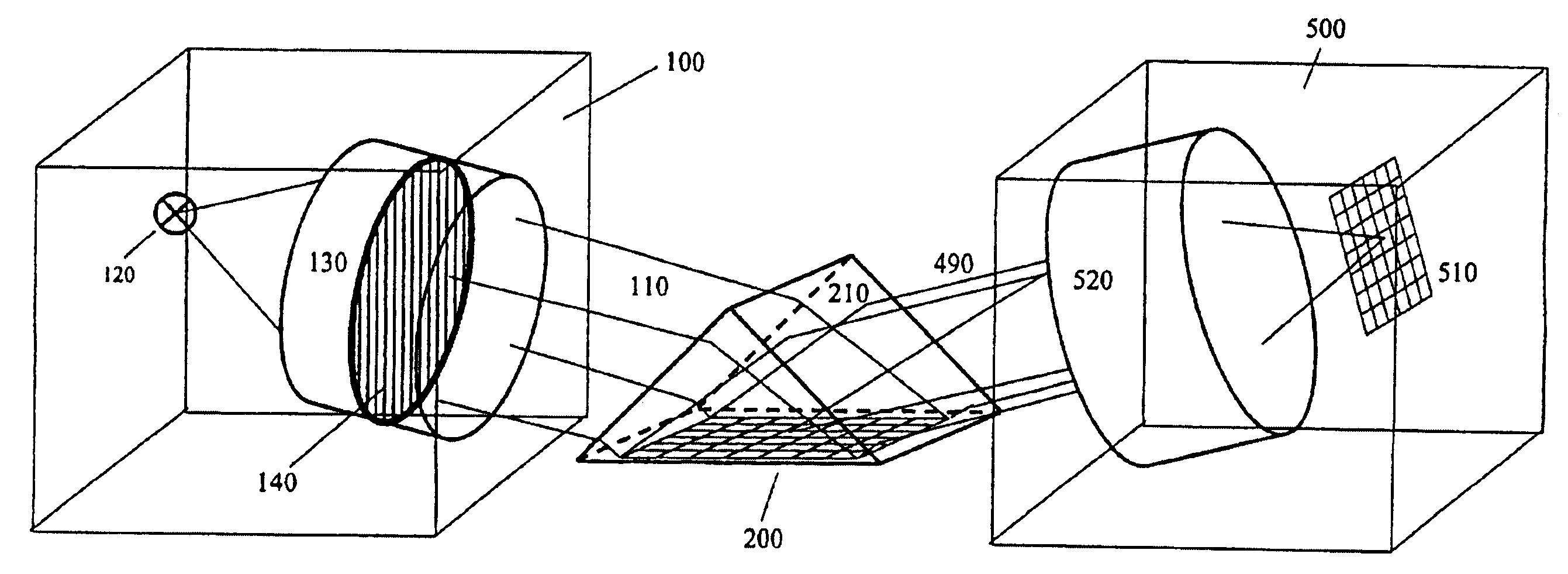
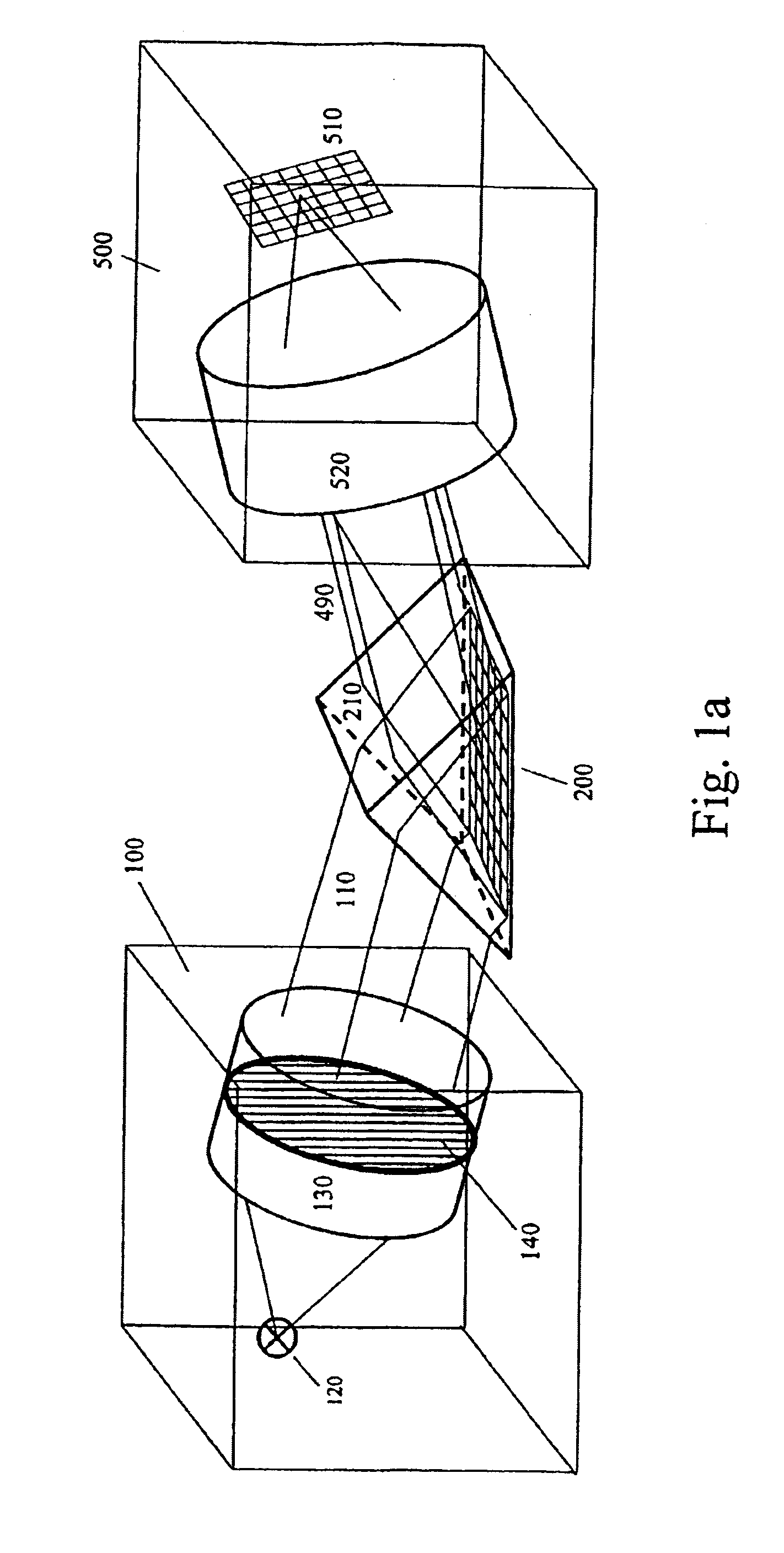
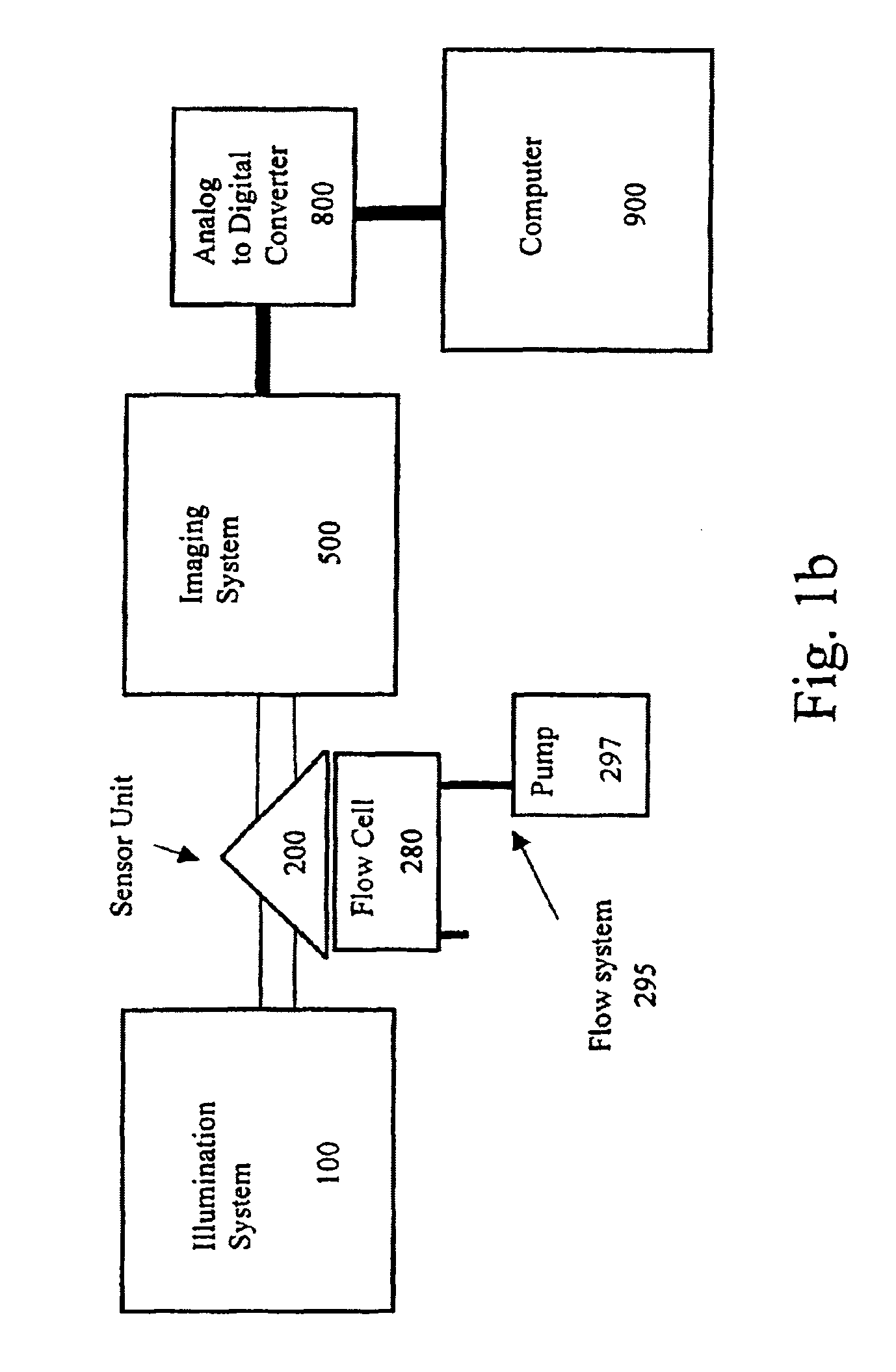
A two-dimensional imaging surface plasmon resonance (SPR) apparatus for optical surface analysis of a sample area on a sensor surface is disclosed. The apparatus comprises a sensor surface layer of a conductive material that can support a surface plasmon, such as a free electron metal, e.g. gold, silver or aluminum, a source of electromagnetic beams of two or more wavelengths that illuminate a two-dimensional surface area from either the front or the backside of the sensor surface layer, and a detector for simultaneous, or pseudo simultaneous, detection of two or more wavelengths of reflected intensities from the two-dimensional surface area, providing two or more two-dimensional images of the surface area, the two-dimensional images being a function of the effective refractive index at each point on the surface area. The two-dimensional images put together result in a color image. The apparatus is suitable for use in biological, biochemical, chemical and physical testing.

Description

The present invention relates to an apparatus for optical surface analysis of a sample area on a sensor surface. The invention is particularly concerned with a two-dimensional imaging surface plasmon resonance (SPR) apparatus suitable for use in biological, biochemical, chemical and physical testing.BACKGROUND OF THE INVENTIONThere is an interest in surface sensitive techniques for quantifying molecular interactions. Properties that are of interest are e.g. concentration of free analyte in solution, surface concentration of molecules on sensor surface, reaction kinetics between interacting substances, affinity of said substances, allosteric effects or epitope mappings. Examples of interacting substances are antigen-antibody, protein-protein, receptor-ligand, DNA-DNA, DNA-RNA, peptides-proteins, carbohydrates-proteins, glycoproteins-proteins, etc.There are many techniques that are suitable for this task, e.g. surface plasmon resonance (SPR), resonant mirror, grating couplers, interfe...

Claims


Application Information

Patent Timeline
Patent Type & Authority Patents(United States)
IPC IPC(8): G01N21/55G01N21/05C12M1/00C12N15/09G01N21/27G01N21/35
CPCG01N21/553
Inventor JOHANSEN, KNUT
Owner SPRING SYST
Learn More