Three-dimensional shape measuring method, and three-dimensional shape measuring apparatus

a three-dimensional shape and measuring method technology, applied in the direction of measuring devices, instruments, using optical means, etc., can solve the problems of reducing the reliability of the measurement result, reducing the quantity of light, and difficult to adjust the focus in every area of the object for measurement, so as to increase the focal depth and high accuracy

Inactive Publication Date: 2005-03-01
MURATA MFG CO LTD
View PDF18 Cites 28 Cited by
  • Summary
  • Abstract
  • Description
  • Claims
  • Application Information

AI Technical Summary

Benefits of technology

The present invention has been made in light of the above problems, and the present invention provides a three-dimensional shape measuring method and a three-dimensional shape measuring apparatus in which degradation of the quantity of light is small, and measurement can be performed with high accuracy by increasing the focal depth of multi-slit light.
According to the above method, the slit light is stopped asymmetrically in the slit direction and in the direction perpendicular thereto. The focal depth in the optical system can be increased thereby. While a diaphragm is conventionally used in order to increase the focal depth, this diaphragm has circular and regular polygonal apertures, and the size in the longitudinal direction is equal to the size in the transverse direction. In other words, the light is limited similarly both in the longitudinal direction and in the transverse direction, and the quantity of light is considerably reduced. Contrary to this, in the above method, the directional slit light is stopped asymmetrically in the slit direction and in the direction perpendicular thereto, so that the degree of reduction of the quantity of light can be reduced. Accordingly, the focal depth in the projection optical system can be increased while mitigating the reduction of the quantity of light, so that the three-dimensional shape of an electronic component, a solder bump, a conductive paste, etc. which requires excellent resolution in the height direction can be measured with high accuracy.
In the above measuring method, the light source is preferably less coherent than a laser beam, and more preferably, may be a white light source. Since the light source less coherent than laser beam, in particular, a white light source, is used, measurement of higher accuracy can be performed in the measurement of the three-dimensional shape of an object for measurement such as an electronic component, a solder bump, a conductive paste, etc., with highly precise height resolution.
In addition, in a conventional system which forms multi-slit light by using a laser beam, a scanning mechanism and the control thereof are required. Contrary to this, in the method of the present invention, only projection is required via the slit pattern in order to form the multi-slit light by using a light source less coherent than a laser beam, so that the configuration is simplified, and a measuring apparatus is inexpensive.
In the above configuration, the asymmetric diaphragm is provided to increase the focal depth in the optical system. While a diaphragm is conventionally used in order to increase the focal depth, this diaphragm has circular and regular polygonal apertures, and the size in the longitudinal direction is equal to the size in the transverse direction. In other words, the light is limited similarly both in the longitudinal direction and in the transverse direction, and the quantity of light is considerably reduced. Contrary to this, in the above configuration, the asymmetric diaphragm is used for stopping the directional slit light primarily in the direction (the transverse direction) perpendicular to the slit direction (the longitudinal direction). In other words, an aperture of a small size may be formed in the transverse direction. The degree of reduction of the quantity of light limited by this asymmetric diaphragm can thus be reduced. Accordingly, the focal depth in the projection optical system can be increased while mitigating the reduction of the quantity of light, so that the three-dimensional shape of an electronic component, a solder bump, a conductive paste, etc. which requires excellent resolution in the height direction can be measured with high accuracy.

Problems solved by technology

When the multi-slit light is projected on the object for measurement in order to enable the measurement of the three-dimensional shape with high accuracy, it is necessary to adjust the focus on the object for measurement, and to project the multi-slit light without any blur Differences in the heights of objects for measurement, for example, may make it difficult to adjust the focus in every area of the object for measurement when projecting the multi-slit light.
However, there is a disadvantage that the quantity of light is reduced.
If the quantity of light is too small, reliability of the result of measurement is degraded, and measurement of high accuracy cannot be performed.

Method used


Image

  • Three-dimensional shape measuring method, and three-dimensional shape measuring apparatus
  • Three-dimensional shape measuring method, and three-dimensional shape measuring apparatus
  • Three-dimensional shape measuring method, and three-dimensional shape measuring apparatus

Examples


first embodiment

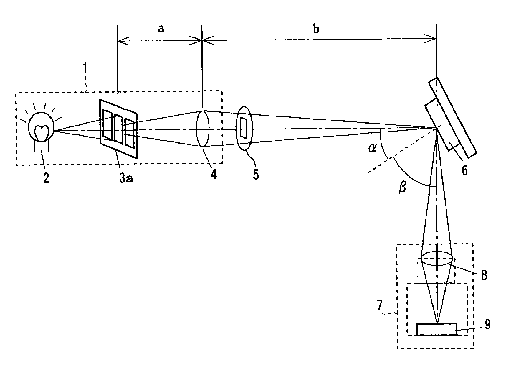
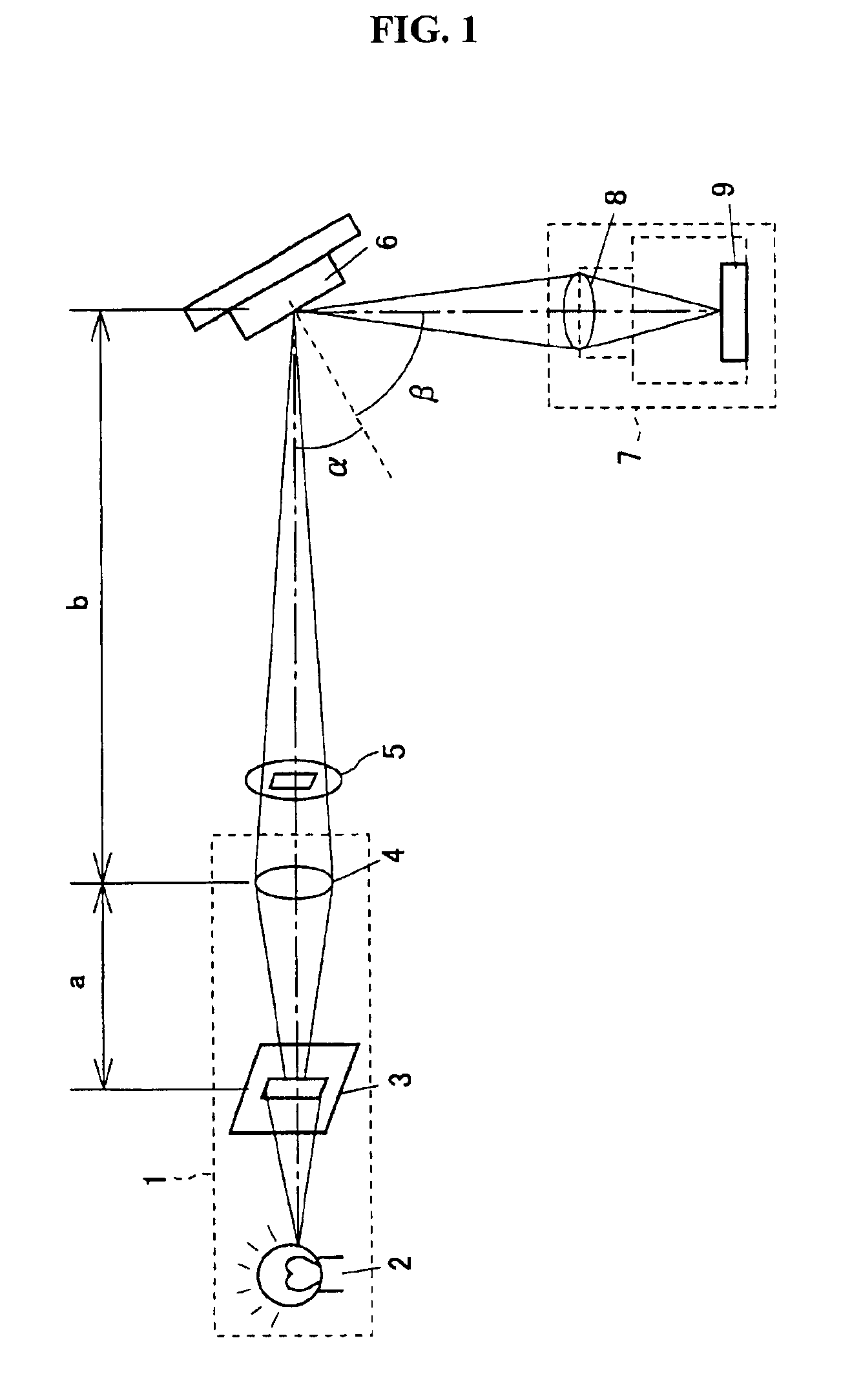
FIG. 1 is a schematic view of a three-dimensional shape measuring method and a three-dimensional shape measuring apparatus according to a first embodiment of the present invention. In the three-dimensional shape measuring apparatus, a projection optical system 1 is provided as shown in FIG. 1. The projection optical system 1 comprises a light source 2, a pattern forming unit 3 which is an optical slit, and a projection lens 4 which is, for example, a collective lens of the focal length f=48 mm.

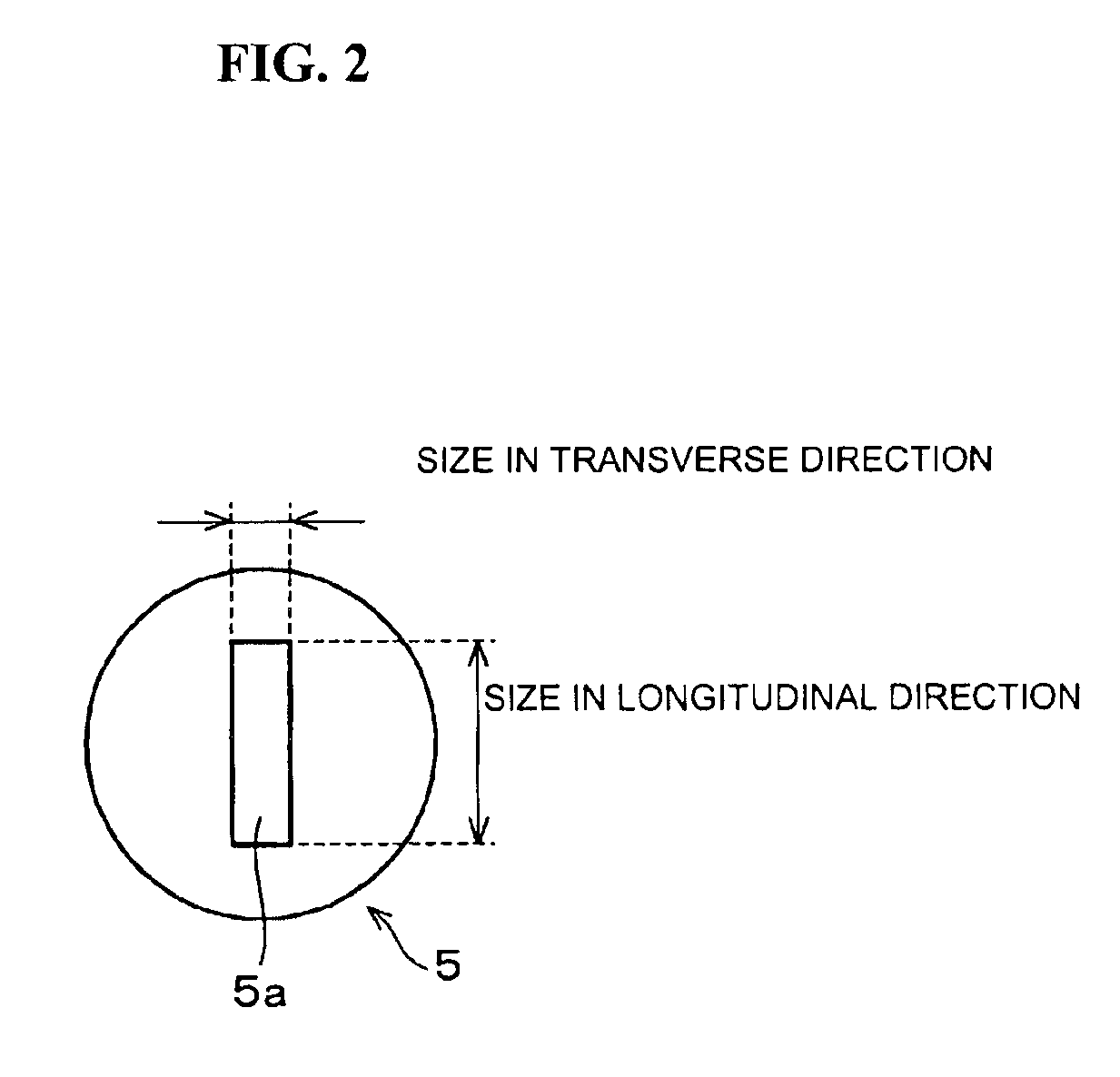
In addition, an asymmetric diaphragm (a diaphragm) 5 is provided between the projection lens 4 and an object 6 for measurement. This asymmetric diaphragm 5 has a rectangular aperture 5a (FIG. 2) in which the size in its transverse direction, which is perpendicular to the longitudinal direction of the slit of the pattern forming unit 3, is smaller than the size in the direction parallel to the slit direction as shown in FIG. 2. In other words, the asymmetric diaphragm 5 has a configuration such...

second embodiment

A three-dimensional shape measuring method and a three-dimensional shape measuring apparatus according to a second embodiment of the present invention will be described below. FIG. 6 is a schematic view of the three-dimensional shape measuring apparatus according to the second embodiment of the present invention. In the three-dimensional shape measuring apparatus, the light source 2, a pattern forming unit 3a of a plurality of slits, and the projection lens 4 are provided in the projection optical system 1 as shown in FIG. 6. In each embodiment described below, components according to the present embodiment which are identical to or correspond to those in the first embodiment are represented by the same reference numerals, and a detailed description thereof is omitted.

The pattern forming unit 3a is shown in FIG. 7. It comprises a light shielding unit 13 and a light shielding unit 14, and the light can be transmitted through only the light shielding unit 14. The light emitted from th...

third embodiment

A three-dimensional shape measuring apparatus according to a third embodiment of the present invention will be described with reference to FIGS. 8 and 9.

As shown in FIG. 8, a mirror (a reflective optical system) 15 to reflect the reflected light is further provided on the three-dimensional shape measuring apparatus on the optical path between the object 6 and the image pickup optical system (detection unit) 7 so that the optical axis of the irradiated light from the projection optical system 1 is substantially parallel to the optical axis of the reflected light from the object 6 incident on the image pickup optical system (detection unit) 7.

By providing this mirror 15, the size of the entire measuring apparatus (in the longitudinal direction in FIG. 8, i.e., in the direction orthogonal to the optical axis of the light reaching the object 6 from the projection optical system 1) can be set to be small.

A modification of the three-dimensional shape measuring apparatus will be described ...


PUM


Abstract

A three-dimensional shape measuring method and a three-dimensional shape measuring apparatus of excellent measurement accuracy. An optical system comprises a light source, a pattern forming unit which is disposed on the optical axis of the light source to form slit light from the light from the light source, and a projection lens to collect the slit light on the object for measurement. An asymmetric diaphragm having an aperture in which the size in the direction perpendicular to the slit direction is smaller than the size in the slit direction is provided in order to stop the slit light. An image pickup optical system is provided to measure the three-dimensional shape of the object for measurement on the basis of the slit light reflected from the object for measurement.

Description

BACKGROUND OF THE INVENTION1. Field of the InventionThe present invention relates to a three-dimensional shape measuring method and a three-dimensional shape measuring apparatus for measuring a three-dimensional shape of an electronic component, a solder bump, or a conductive paste, for example, by a light-section method.2. Description of the Related ArtRequests have been made for carrying out 100% inspection of objects for measurement such as electronic components in a non-destructive manner and measuring a three-dimensional shape of an object in a non-contact manner in order to rapidly carry out the inspection. A light-section method is known as one of these measuring methods.The above light-section method is a method of projecting a slit light on the object on a measurement table, taking in a beam-split image reflected by the object by a camera as image data, and obtaining a three-dimensional shape (such as a position of unevenness) on a surface of the object by the principle of ...

Claims


Application Information

Patent Timeline
Patent Type & Authority Patents(United States)
IPC IPC(8): G01B11/25G01B11/24
CPCG01B11/25
Inventor YANAGISAWA, KUNIAKINISHIKI, RYO
Owner MURATA MFG CO LTD
Why Eureka
Try Eureka