Transparent optical switch

a transparent optical switch and optical network technology, applied in the field of communication systems, can solve the problems of limited ability to examine and extract necessary information carried within the optical signal, inability to achieve the bandwidth, and inability to meet the requirements of bandwidth, etc., to achieve the effect of achieving the bandwidth, the control of the optical network is relatively complex, and the network management is adequate. , the effect of reducing the cost of operation

Inactive Publication Date: 2005-03-01
AMERICAN TELEPHONE & TELEGRAPH CO
View PDF21 Cites 34 Cited by
  • Summary
  • Abstract
  • Description
  • Claims
  • Application Information

AI Technical Summary

Benefits of technology

In a further aspect of the invention, an optical switch includes first and second switch fabrics for providing 1:2 broadcast capability. Each switch input port splits an input signal into a first signal received by the first switch fabric and a second signal received by the second switch fabric. In normal operation, the same output port receives the first and second signals and selects only one so that if one of the switch fabrics fails, the output port can select the signal from the operational switch fabric. Thus, the first and second switch fabrics provide redundancy.

Problems solved by technology

However, switches that convert data from the optical domain to the electrical domain and back to the optical domain can create an impediment to achieving the bandwidths that developing optical networking technologies potentially offer.
One disadvantage associated with known transparent optical switches is the limited ability to examine and extract necessary information carried within the optical signal.
Thus, adequate network management, performance monitoring, and control within the optical network is relatively complex, costly, and unreliable.

Method used


Image

  • Transparent optical switch
  • Transparent optical switch
  • Transparent optical switch

Examples


Embodiment Construction

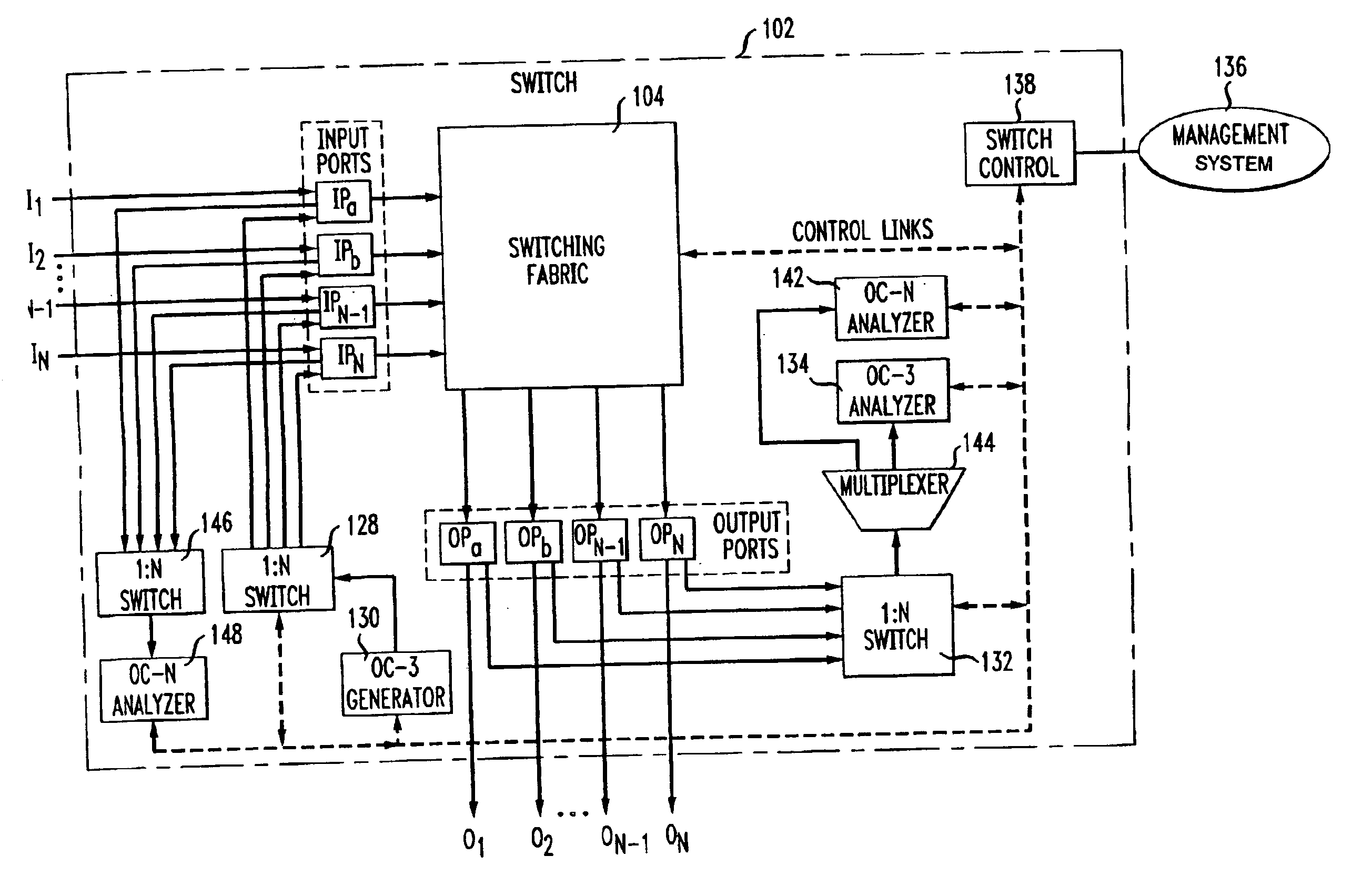
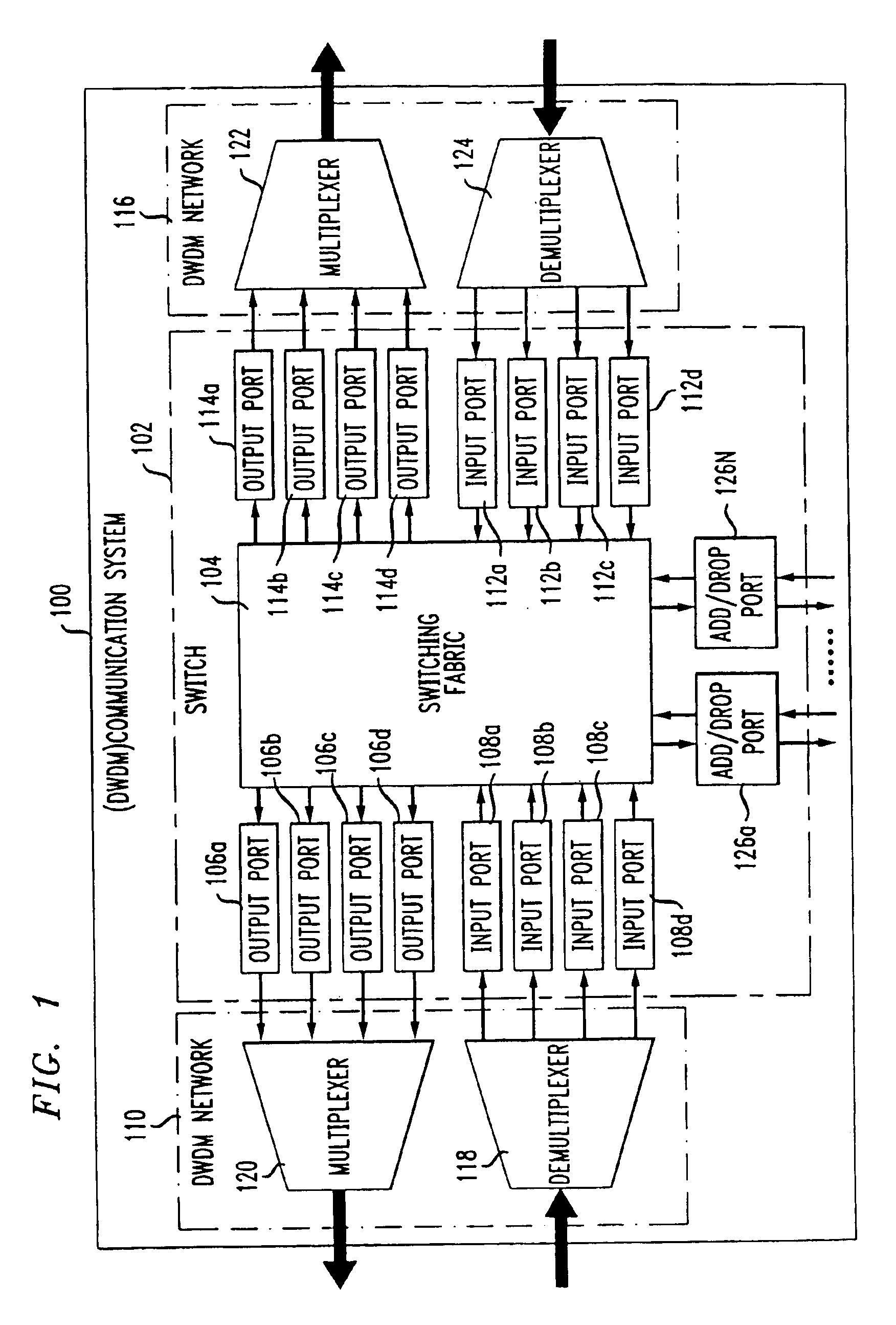
FIG. 1 shows a portion of a dense wave division multiplexing (DWDM) communication system 100 having a transparent optical switch 102 in accordance with the present invention. As used herein, transparent and non-blocking optical switches refer to optical switches that do not convert optical signals to electrical signals for signals that pass through the switch, i.e., not add / drop signals. The switch 102 includes switching fabric 104 that interfaces with a first set of output ports 106a-d and a first set of input ports 108a-d coupled to a first DWDM network 110. A second set of input ports 112a-d and a second set of output ports 114a-d are coupled to a second DWDM network 116. The ports 106,108,112,114, in combination with the switching fabric 104 provide bi-directional communication between the first and second DWDM networks 110,116.

The first set of input ports 108 receive respective channel data from a first DWDM demultiplexer 118 and the first set of output ports provide channel da...


PUM


Abstract

A transparent optical switch includes network management and performance monitoring using bit level information obtained by extracting selected information on a polling basis and analyzing the extracted information in the electrical domain. In one embodiment, a signal is injected into the switch fabric of the switch via a demultiplexing device. The injected signal is extracted at the output of the switching fabric via an N:1 switch and analyzed by a signal analyzer to verify input to output connections. In another embodiment, an optical switch includes first and second switch fabrics for 1:2 broadcast capability. In a further embodiment, an optical communication system includes a plurality of optical networks and a plurality of optical switches that cooperate to generate unequipped signals and to obtain autonomously switch-to-switch port connectivity information required for auto-topology discovery.

Description

STATEMENT REGARDING FEDERALLY SPONSORED RESEARCHNot Applicable.FIELD OF THE INVENTIONThe present invention relates generally to communication systems, and more particularly, to optical communication networks.BACKGROUND OF THE INVENTIONConventional optical networks generally include switch devices that provide a connection between an input port and an output port to establish a channel between first and second optical links. Such switches typically convert the optical signals to electrical signals to make the input / output connections. The switch examines the data stream at a bit level to perform network management and performance monitoring functions. For example, frame headers can contain source and destination information used to route a constant bit-rate data stream in the network. Performance monitoring can include examining selected overhead data to detect and isolate errors within the network.However, switches that convert data from the optical domain to the electrical domain a...

Claims


Application Information

Patent Timeline
Patent Type & Authority Patents(United States)
IPC IPC(8): H04L12/56H04Q11/04H04Q11/00H04B10/035H04B10/27H04Q3/52H04J14/00H04J14/02
CPCH04J14/0206H04J14/0212H04Q1/24H04Q11/0478H04Q11/0005H04J2203/0057H04L2012/5625H04L2012/5628H04Q2011/0083H04Q2011/0016H04Q2011/0024H04Q2011/0033H04Q2011/0043
Inventor CHAUDHURI, SIDGOLDSTEIN, EVAN L.
Owner AMERICAN TELEPHONE & TELEGRAPH CO
Why Eureka
Try Eureka