Method and apparatus for concurrently estimating respective directions of a plurality of sound sources and for monitoring individual sound levels of respective moving sound sources

a technology of plurality of sound sources and simultaneous estimation, applied in direction/deviation determination systems, instruments, reradiation, etc., can solve the problem of low accuracy of estimating the direction of sound sources, and achieve the effect of accurate estimation

Inactive Publication Date: 2005-03-01
PANASONIC CORP
View PDF11 Cites 48 Cited by
  • Summary
  • Abstract
  • Description
  • Claims
  • Application Information

AI Technical Summary

Benefits of technology

It is an objective of the present invention to overcome the above problems of the prior art, by providing a method and apparatus for sound source direction estimation which enables the direction of a sound source in relation to a specific point to be accurately estimated even when there is a plurality of sound sources in the vicinity, or a sound source of a type other than other than desired sound sources.
To achieve the above objective of obtaining estimated directions of one or more sound sources, with a sound source direction estimation method and apparatus according to the present invention, the input signals of an array of microphones are extracted in each of respective time windows, while in each of the time windows, respective sound source estimated directions are calculated for each of a frequency of a fixed set of frequencies, and the average of the directions thus calculated becomes the estimated direction corresponding to that time window. Since a sound source estimated direction is obtained based on a plurality of frequencies, a high degree of sound source direction estimation accuracy can be achieved.
To further increase the accuracy of sound source direction estimation, as each frequency-averaged estimated direction is obtained as described above for a time window, the average of the estimated direction obtained for the time window and the respectively estimated directions which have been calculated for a fixed plurality of time windows which precede that time window is calculated, to thereby obtain (for each of successive time windows) an estimated direction which is based on both frequency-averaging and time-averaging.
Furthermore, with such a sound source direction estimation method and apparatus according to the present invention, a judgement can be made as to whether the direction of a sound source has passed through a specific direction, and data expressing a passage detection result then generated to indicate that fact, by detecting whether a number of estimated directions obtained for that sound source which are each within a fixed range of directions and occur within a fixed observation interval exceeds a predetermined minimum number. In that way, it becomes possible to detect that a moving sound source is currently passing the microphone array.
Furthermore, with such a sound source direction estimation method and apparatus according to the present invention it becomes possible to judge the direction of motion of a sound source, when a passage detection result corresponding to the sound source is generated, based upon the sign of the difference between estimated directions respectively obtained for the sound source before and at the time point at which the passage detection result is generated. For example, successive sets of obtained estimated directions can be temporarily set into a data buffer, so that when a passage detection result is obtained, the buffer contents will contain estimated directions which were obtained prior to the point of generating the passage detection result. Alternatively, it may be possible to achieve a similar effect by using an estimated direction which is obtained subsequent to the time at which the passage detection result is obtained.

Problems solved by technology

However with such a prior art type of sound source direction estimation method, when sounds from a plurality of sources are simultaneously reaching the microphones, or when there is a sound source other than the sound sources which it is desired to monitor, then the accuracy of estimating the direction of a sound source will become low.

Method used


Image

  • Method and apparatus for concurrently estimating respective directions of a plurality of sound sources and for monitoring individual sound levels of respective moving sound sources
  • Method and apparatus for concurrently estimating respective directions of a plurality of sound sources and for monitoring individual sound levels of respective moving sound sources
  • Method and apparatus for concurrently estimating respective directions of a plurality of sound sources and for monitoring individual sound levels of respective moving sound sources

Examples


first embodiment

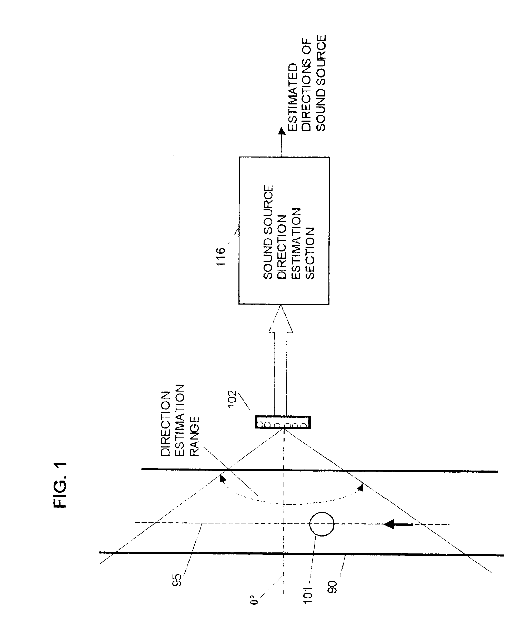
The basic features of a first embodiment of the invention will first be described referring to the conceptual diagram of FIG. 1. In FIG. 1, numeral 101 denotes a sound source such as a motor vehicle (as seen in plan view) travelling along a path 95 in the direction indicated by the arrow, for example along a road 90. A linear array of a plurality of microphones 102 is disposed adjacent to the path 95 with the array direction parallel to the path. Respective output signals from the microphones of array 102 are supplied to a sound source direction estimation section 116, in which the signals are processed to detect successive directions (expressed with respect to a specific point as origin, such as the location of a central microphone of the microphone array 102) of each of one or more sound sources such as the sound source 101 which are moving in the arrow direction along the path 95 within the indicated direction estimation range.

Each direction of a sound source will be assumed to b...

second embodiment

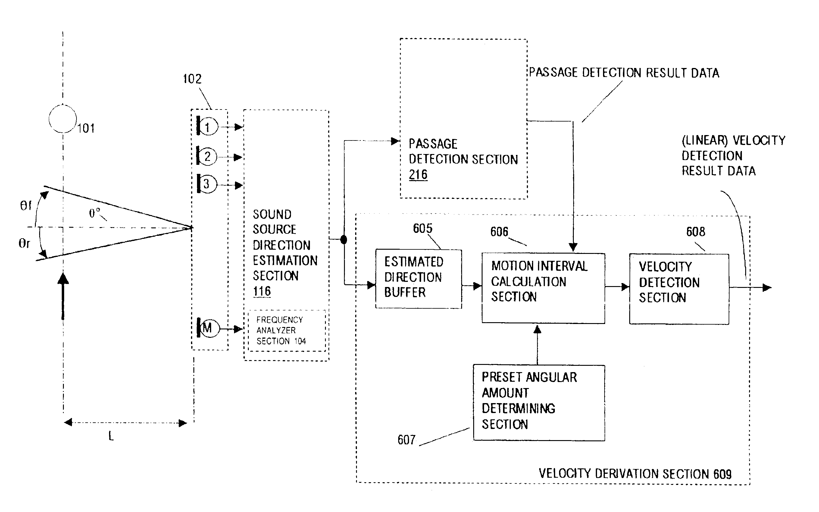
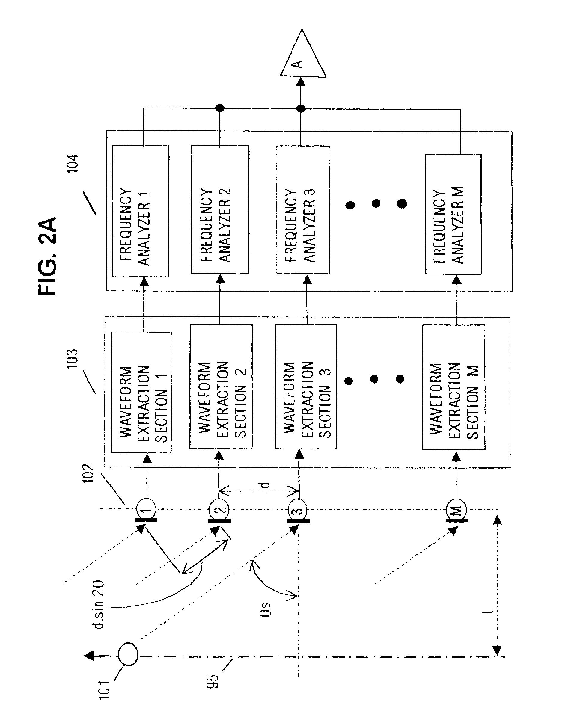
A second embodiment of the invention will be described referring first to the general system block diagram of FIG. 6. In FIG. 6, a microphone array 102 and a sound source direction estimation section 116 have the respective functions and configurations described hereinabove for the correspondingly numbered components of the first embodiment. The sound source direction estimation section 116 can have the first configuration shown in FIGS. 2A, 2B, whereby each output estimated direction is derived based upon frequency-based averaging and upon time-based averaging applied over a plurality of successive time windows, or can have the alternative configuration shown in FIG. 4, with only frequency-based averaging being applied. Data expressing respective estimated directions of a sound source are supplied from the sound source direction estimation section 116 to an in-range occurrence number calculation section 212 of a passage detection section 216, which also consists of a direction rang...

third embodiment

A third embodiment will be described referring to the general system block diagram of FIG. 8. As shown, this is formed of a microphone array 102, sound source direction estimation section 116 and passage detection section 216, together with a data buffer 307, a data extraction section 308 and a recording apparatus 309. The sound source direction estimation section 116 can have the first configuration shown in FIGS. 2A, 2B, whereby each output estimated direction is derived based upon frequency-based averaging and upon time-based averaging applied over a plurality of successive time windows, or can have the alternative configuration shown in FIG. 4, with only frequency-based averaging being applied. The passage detection section 216 has the configuration and operation described above for the preceding embodiment.

The operation of this embodiment is as follows. Data expressing respective passage detection results are supplied from the passage detection section 216 to the data extractio...


PUM


Abstract

A method and apparatus enabling information including respective angular directions to be obtained for one or more sound sources includes a sound source direction estimation section for frequency-domain and time-domain processing of sets of output signals from a microphone array to derive successive estimated angular directions of each of the sound sources. The estimated directions can be utilized by a passage detection section to detect when a sound source is currently moving past the microphone array and the direction of the sound source at the time point when such passage detection is achieved, and a motion velocity detection section which is triggered by such passage detection to calculate the velocity of the passing sound source by using successively obtained estimated directions. In addition it becomes possible to produce directivity of the microphone array, oriented along the direction of a sound source which is moving past the microphone array, enabling accurate monitoring of sound levels of respective sound sources.

Description

BACKGROUND OF THE INVENTION1. Field of the InventionThe present invention relates to a method and apparatus for estimating the respective angular directions of one or more sound sources in relation to a specific position, and to a method and apparatus for using such estimated directions to detect when a moving sound source has moved through a specific angular direction and to monitor the sounds emitted from respective ones of a plurality of moving sound sources.2. Description of the Prior ArtOne method of estimating the angular direction of a sound source and of monitoring a sound source is described in Japanese patent HEI 5-114098. FIG. 22 shows the configuration of this prior art sound source direction estimation apparatus. In FIG. 22, first and second directional microphones 901 and 902 are set up spaced apart by a fixed distance L, along a line of flow of traffic. The sounds which are respectively gathered by these microphones, which can be referred to as traffic noise A and tra...

Claims


Application Information

Patent Timeline
Patent Type & Authority Patents(United States)
IPC IPC(8): G01S3/00G01S3/808G01V1/00G01S11/00G01S11/14G01S3/802
CPCG01S3/8086G01V1/00G01S11/14
Inventor MIZUSHIMA, KOICHIRO
Owner PANASONIC CORP
Why Eureka
Try Eureka