Piston

a technology for internal combustion engines and pistons, which is applied to engine components, trunk pistons, pistons, etc., can solve the problems of major stress in the transition area between pistons, insufficient support of piston pin bosses, and a tendency to produce a rigid or stiff support for skirt sections

Inactive Publication Date: 2005-03-08
BRP ROTAX
View PDF15 Cites 27 Cited by
  • Summary
  • Abstract
  • Description
  • Claims
  • Application Information

AI Technical Summary

Benefits of technology

[0017]It is another object of the present invention to provide a low-weight durable piston that minimizes stress in the transition area between the piston pin bosses and the piston head.
[0018]It is another object of the present invention to provide a low-weight durable piston that provides flexible or soft support for the piston skirt.
[0019]It is another object of the present invention to provide a low-weight durable piston that minimizes stress in the transition area between the piston pin bosses and the piston head while providing flexible or soft support for the piston skirt.
[0027]In response to the foregoing challenges, applicants have developed a piston for an internal combustion engine that minimizes the stresses found in a transition area between the piston head and the associated piston pin bosses while maintaining a flexible soft connection between the piston skirts and the piston head.

Problems solved by technology

These connecting walls, however, do not optimally support the piston pin bosses.
This arrangement, also, causes major stresses in the transition area between the piston pin bosses and the underside of the piston head.
This construction, however, produces a rather rigid or stiff support for the skirt sections.
This produces piston noise.
The piston pin bosses, however, are not joined to the underside of the piston head in an optimal manner.
As such, major stresses can occur in the transition area between the piston pin bosses and the underside of the piston head, which may lead to cracking in extreme operating conditions.
With the Ω-piston arrangement, although the support for the skirt sections is relatively flexible, the stress distribution in the transition area between the piston boss and the underside of the piston head is not favorable.

Method used


Image

  • Piston
  • Piston
  • Piston

Examples


Embodiment Construction

ng curve is convexly curved. It is more preferable that at least 50% of the connecting wall along the length of the second intersecting curve is convexly curved.

BRIEF DESCRIPTION OF THE DRAWINGS

[0034]The invention will be described in conjunction with the following drawings in which like reference numerals designate like elements and wherein:

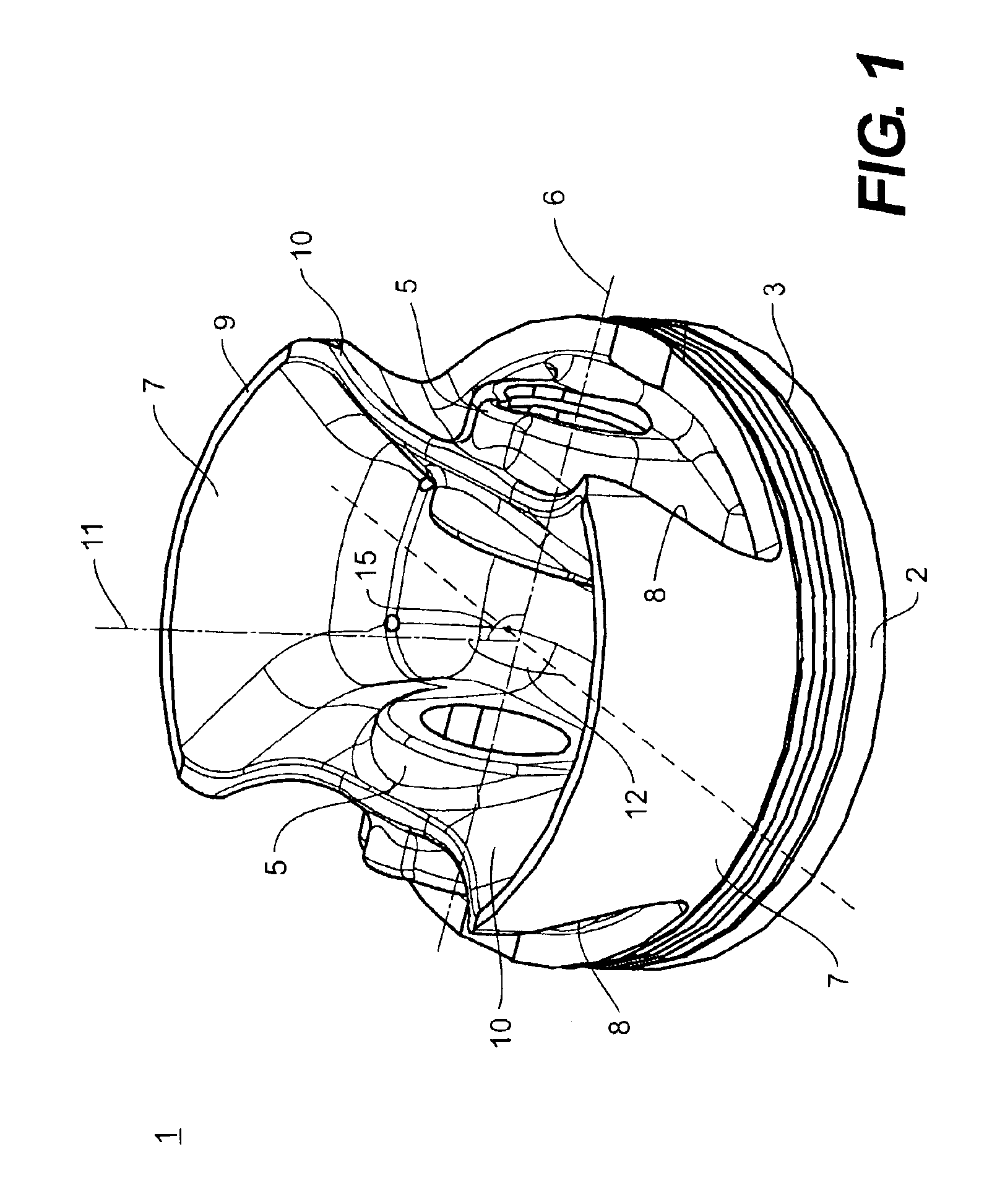
[0035]FIG. 1 is an oblique perspective view of a bottom of a piston in accordance with the present invention;

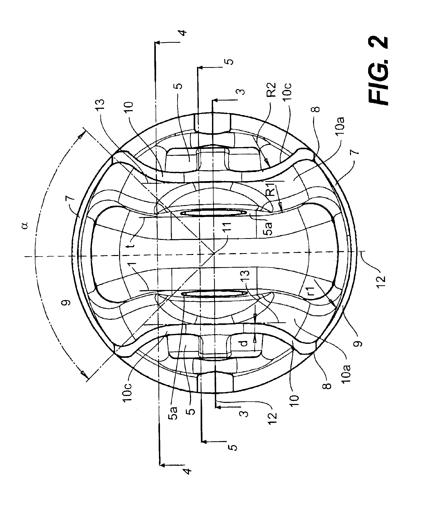
[0036]FIG. 2 is a bottom of the piston of FIG. 2;

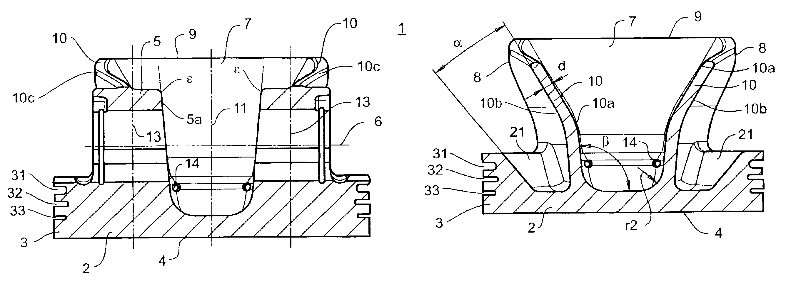
[0037]FIG. 3 is a cross sectional view of the piston of FIG. 2 along section line 3—3;

[0038]FIG. 4 is a cross sectional view of the piston of FIG. 2 along section line 4—4;

[0039]FIG. 5 is a cross sectional view of the piston of FIG. 2 along section line 5—5;

[0040]FIG. 6 a side view of the piston of FIG. 1; and

[0041]FIG. 7 is a cross sectional view of the piston of FIG. 6 along section line 7—7.

DETAILED DESCRIPTION OF PREFERRED EMBODIMENTS

[0042]A piston 1 in accordance with the present inven...


PUM


Abstract

A light weight piston for an internal combustion engine is disclosed that minimizes the stresses found in a transition area between the piston head and the associated piston pin bosses while maintaining a flexible soft connection between the piston skirts and the piston head. The piston includes a pair of piston skirts having tapered edges. Flared connecting walls are provided such that the distance between the connecting walls is minimized adjacent a pair of piston pin bosses and the distance between the connecting walls is maximized adjacent a portion of the tapered edges. The connecting wall flares in a generally outward direction such that at least a portion of the inner surfaces of the connecting wall has a generally convex curvature.

Description

CROSS REFERENCE TO RELATED APPLICATIONS[0002]This application claims priority to U.S. Provisional Patent Application No. 60 / 366,527, which was filed on Mar. 25, 2002.BACKGROUND OF THE INVENTION[0003]1. Field of the Invention[0004]The present invention relates to pistons for internal combustion engines. In particular, the present invention relates to a piston having configuration that achieves flexible support of the skirt sections of the piston while minimizing stresses in a transition area between the piston bosses and the piston head.[0005]2. Description of Related Art[0006]In an internal combustion engine, each cylinder has piston slidably received therein. The piston is operatively connected to a crankshaft in a crankcase through a connecting rod. The connecting rod is typically connected to the piston by a piston pin. The piston pin is received within a pair of piston pin bosses that are either formed in or connected to the piston. Typically, pistons are formed with skirt secti...

Claims


Application Information

Patent Timeline
Patent Type & Authority Patents(United States)
IPC IPC(8): F02F3/02F02F3/00
CPCF02F3/0076F02F3/022F02F3/02
Inventor GLINSNER, KARLOLEJNICZAK, MARTIN
Owner BRP ROTAX
Why Eureka
Try Eureka