Printer that incorporates a binding apparatus for binding sheets

Inactive Publication Date: 2005-03-08
SILVERBROOK RES PTY LTD +1
View PDF48 Cites 26 Cited by
  • Summary
  • Abstract
  • Description
  • Claims
  • Application Information

AI Technical Summary

Benefits of technology

The binding mechanism may include a vibration imparting mechanism for imparting vibratory mo

Problems solved by technology

This is a time consuming an

Method used


Image

  • Printer that incorporates a binding apparatus for binding sheets
  • Printer that incorporates a binding apparatus for binding sheets
  • Printer that incorporates a binding apparatus for binding sheets

Examples


Embodiment Construction

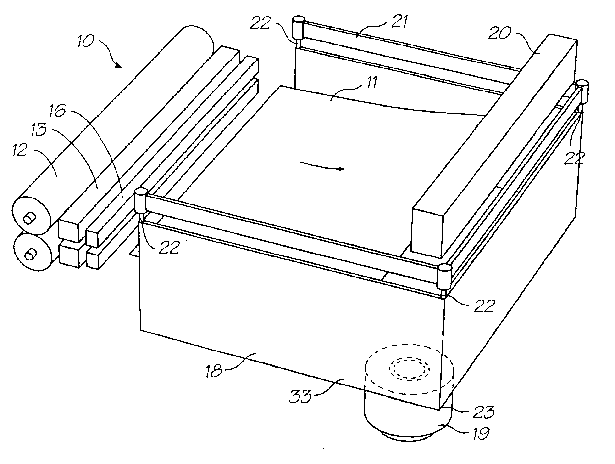
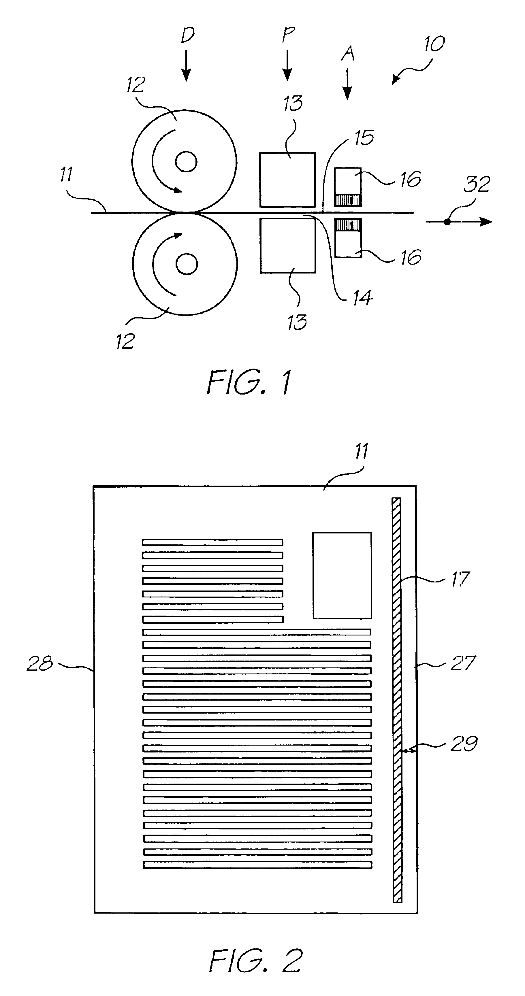
In FIG. 1, reference numeral 10 generally indicates a process, in accordance with the invention, by which adhesive is applied to a sheet 11 as the sheet 11 passes through a printer incorporating an adhesive applicator.

A driving station D drives the sheet 11 in the direction of an arrow 32. The driving station D comprises a pair of opposed pinch rollers 12. The sheet 11 is driven through a printing station P and then an adhesive application station A. Alternatively, the adhesive application station A precedes the printing station P. However, it is preferred that the adhesive application station A follow the printing station P so that adhesive on the sheet 11 does not clog a print head or print heads of the printing station P.

For single sided sheet printing, the printing station P comprises a single print head 13. The print head 13 is a pagewidth drop-on-demand ink jet print head. Alternatively, the print head 13 is that of a laser printer or other printing device. If the sheet 11 is ...


PUM

PropertyMeasurementUnit
Fractionaaaaaaaaaa
Speedaaaaaaaaaa

Abstract

A printer includes a roller assembly for feeding sheets of print media along a feed path. A print head is positioned downstream of the roller assembly for carrying out a printing operation on the sheets of print media. An adhesive application mechanism is positioned downstream of the print head and includes first and second aligned adhesive applicators that are positioned on opposite sides of the feed path and are configured to apply adhesive simultaneously to the sheets of media as the sheets pass between the applicators along the feed path, such that the sheets each have aligned strips of adhesive on respective sides. A support structure positioned downstream of the adhesive application mechanism defines a floor onto which sheets to be bound are conveyed and a wall that extends from the floor to define a stop for the sheets that are fed onto the floor. A binding mechanism is arranged on the support structure and is displaceable with respect to the support structure to act on each sheet fed into the support structure such that the sheets are adhered together with the strips of adhesive.

Description

FIELD OF THE INVENTIONThe following invention relates to a printer. More particularly, this invention relates to a printer that incorporates a binding apparatus for binding sheets.BACKGROUND OF THE INVENTIONIt is well known to print individual sheets of a volume to be bound, place all of the printed sheets into a stack, crop one or more edges of the stack and to bind the sheets together by applying a binding adhesive to an edge of the stack of sheets. This is a time consuming and labour-intensive process.It would be more efficient to provide pre-cut, uniformly sized sheets, print one or both surfaces of each sheet and provide a strip of binding adhesive to one or both surfaces of each sheet adjacent the edge to be bound. Then the printed and pre-glued sheets can be placed accurately in a stack, and the sheets adjacent the spine pressed so that the adhesive binds the sheet edges together.It would also be desirable to provide an apparatus and method for applying a strip or strips of b...

Claims


Application Information

Patent Timeline
IPC IPC(8): B41J3/44B42C9/00
CPCB41J3/44B42C9/0081Y10T156/1761Y10S412/90Y10T156/1798Y10S412/901
Inventor SILVERBROOK, KIA
Owner SILVERBROOK RES PTY LTD
Why Eureka
Try Eureka