Sealed ESP motor system

a motor system and sealed technology, applied in the field of pumping systems, can solve problems such as short circuit, electrical short circuit, and protector malfunction

Inactive Publication Date: 2005-03-08
SCHLUMBERGER TECH CORP
View PDF27 Cites 110 Cited by
  • Summary
  • Abstract
  • Description
  • Claims
  • Application Information

AI Technical Summary

Problems solved by technology

Contamination of the clean oil leads to short circuit which is one of the most common failure modes in electric motors used in ESP applications.
Circumstances such as thermal cycli...

Method used


Image

  • Sealed ESP motor system
  • Sealed ESP motor system
  • Sealed ESP motor system

Examples


Embodiment Construction

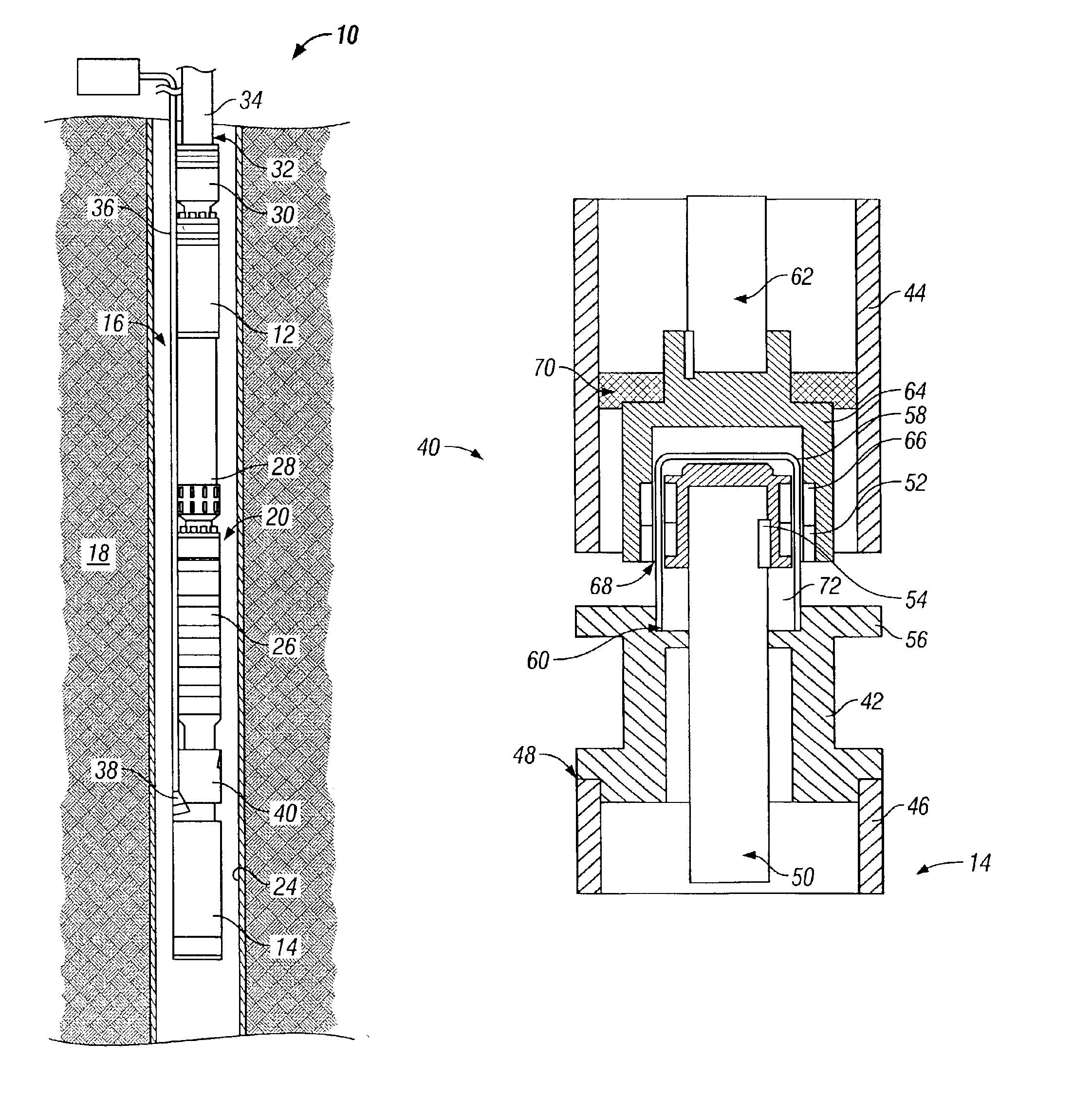
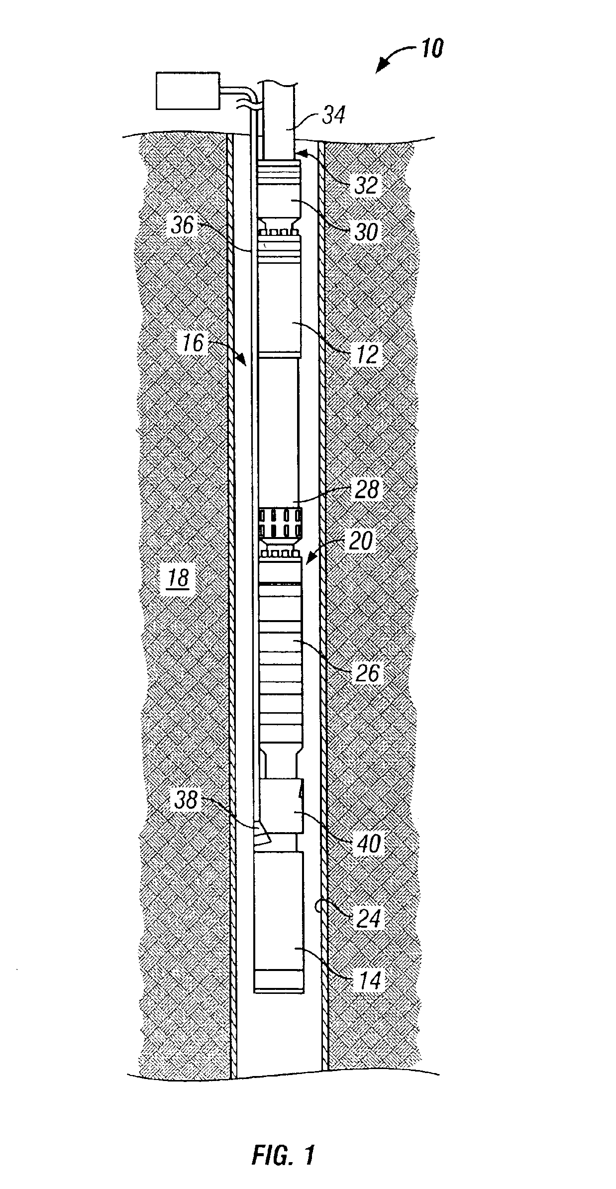
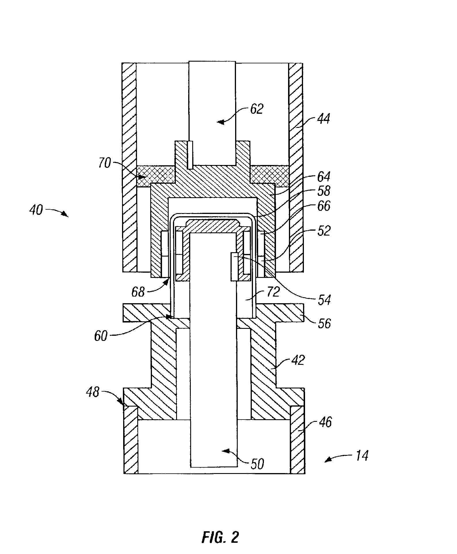
Referring generally to FIG. 1, a submersible pumping system, such as an electric submersible pumping system (ESP), having an embodiment of the sealed motor system 10 of the present invention is illustrated. The submersible pumping system may comprise a variety of components depending on the particular application or environment in which it is used. The sealed motor system 10 used therein includes at least a submersible pump 12 and a submersible sealed motor 14.

The submersible pumping system is designed for deployment in a well 16 within a geological formation 18 containing desirable production fluids, such as petroleum. In a typical application, a wellbore 20 is drilled and lined with a wellbore casing 24. The submersible system is deployed within wellbore 20 to a desired location for pumping of wellbore fluids.

The sealed motor system 10 includes a variety of additional components. A protector 26 serves to transmit torque generated by the motor 16 to the submersible pump 12. The pro...


PUM


Abstract

The present invention provides a submersible motor and pump system for use in a wellbore. More specifically, the present invention provides a submersible system having a sealed motor and a magnetic coupling to transmit torque from the sealed motor to the pump.

Description

FIELD OF THE INVENTIONThe present invention relates generally to pumping systems utilized in raising fluids from wells, and particularly to a submersible pumping system having a sealed motor.BACKGROUND OF THE INVENTIONIn producing petroleum and other useful fluids from production wells, it is generally known to provide a submersible pumping system, such as an electric submersible pumping system (ESP), for raising the fluids collected in a well. Typically, production fluids enter a wellbore via perforations made in a well casing adjacent a production formation. Fluids contained in the formation collect in the wellbore and may be raised by the pumping system to a collection point above the earth's surface. The ESP systems can also be used to move the fluid from one zone to another.An ESP system is generally comprised of a motor section, a pump section, and a protector. Current motor designs require clean oil, not only to minimize magnetic losses, but also to provide appropriate lubric...

Claims


Application Information

Patent Timeline
IPC IPC(8): E21B43/12
CPCE21B43/128F04D13/10F04D13/024
Inventor ARAUX, GRIGORY L.BUCHANAN, STEVEN E.
Owner SCHLUMBERGER TECH CORP
Why Eureka
Try Eureka