Method and system for automated fault reporting

a technology of automatic fault reporting and fault reporting, applied in the field of railways, can solve the problems of increased cost and fail-safe systems

Inactive Publication Date: 2005-03-08
SIEMENS MOBILITY INC
View PDF50 Cites 120 Cited by
  • Summary
  • Abstract
  • Description
  • Claims
  • Application Information

AI Technical Summary

Benefits of technology

The present invention meets the aforementioned need to a great extent by providing a computerized train control system in which a control module gathers maintenance information concerning malfunctioning wayside status devices and automatically reports the maintenance information to an appropriate party. In one embodiment of the invention, the control module uses a positioning system such as a global positioning system and a database including locations of devices in order to determine when the train is near a device. If no status information is received from a wayside status device as a train approaches the device, or the status information transmitted by the device indicates a problem, the train is allowed to continue at a reduced speed to allow the engineer / operator to visually confirm that it is safe for the train to proceed. If the track or device monitored by the wayside status device has been successfully passed, or if the engineer / operator indicates that the track or device monitored by the wayside status device is not a problem, or the wayside status device fails to respond, the control module automatically records a malfunction and reports the malfunction. In highly preferred embodiments, the control module directly reports the malfunction to a central authority such as a dispatcher. Other methods of reporting the malfunction information are used in other embodiments.

Problems solved by technology

Furthermore, many of these systems are fail-safe in that some sort of special procedure must be performed in order for the train to pass a wayside status device if a “good” status information signal is not received from the wayside status device.
However, regardless of the type of special procedure, it will invariably involve additional time, which increases cost.

Method used


Image

  • Method and system for automated fault reporting
  • Method and system for automated fault reporting
  • Method and system for automated fault reporting

Examples


Embodiment Construction

The present invention will be discussed with reference to preferred embodiments of train control systems. Specific details, such as specific algorithms and hardware, are set forth in order to provide a thorough understanding of the present invention. The preferred embodiments discussed herein should not be understood to limit the invention. Furthermore, for ease of understanding, certain method steps are delineated as separate steps; however, these steps should not be construed as necessarily distinct nor order dependent in their performance.

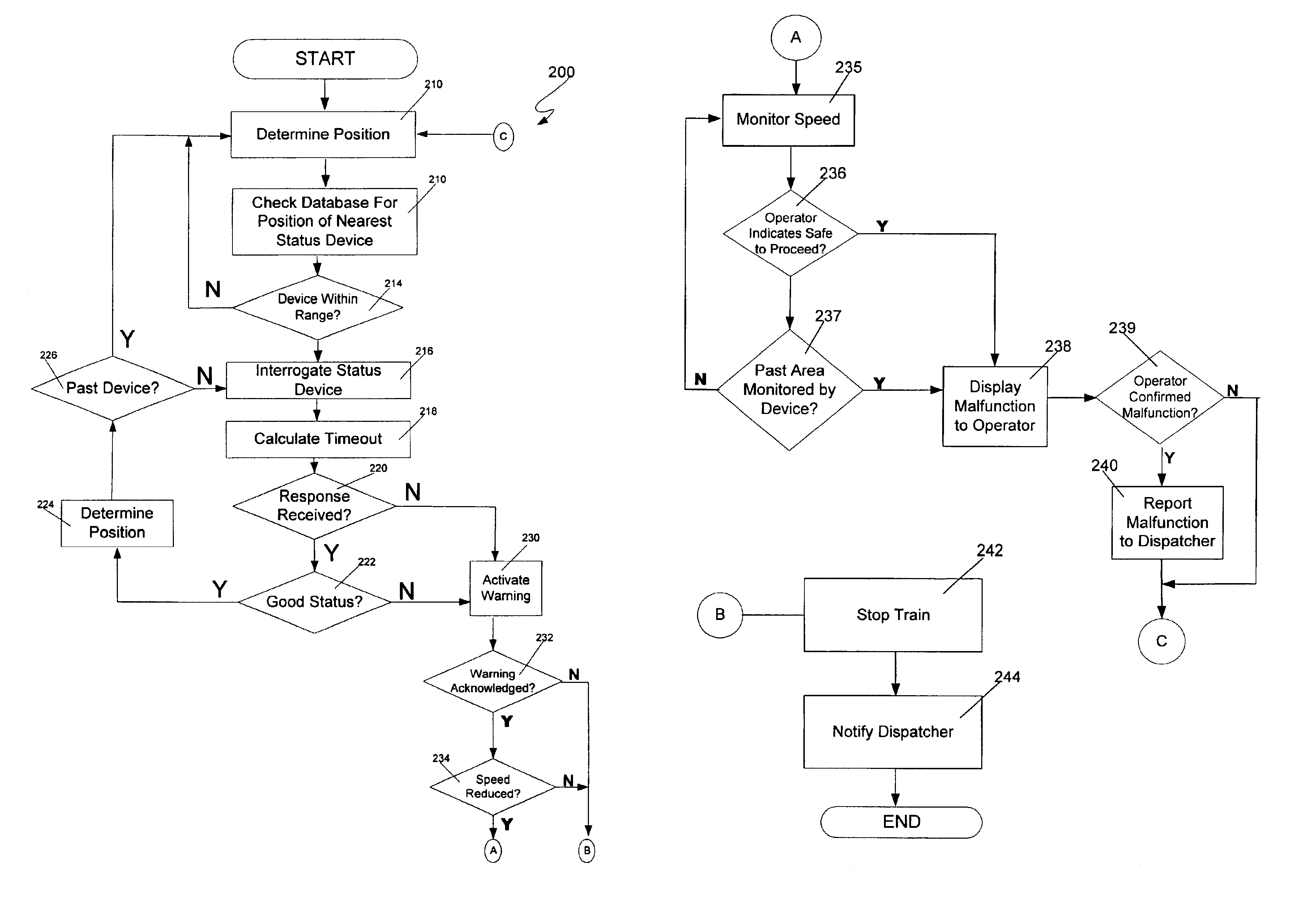
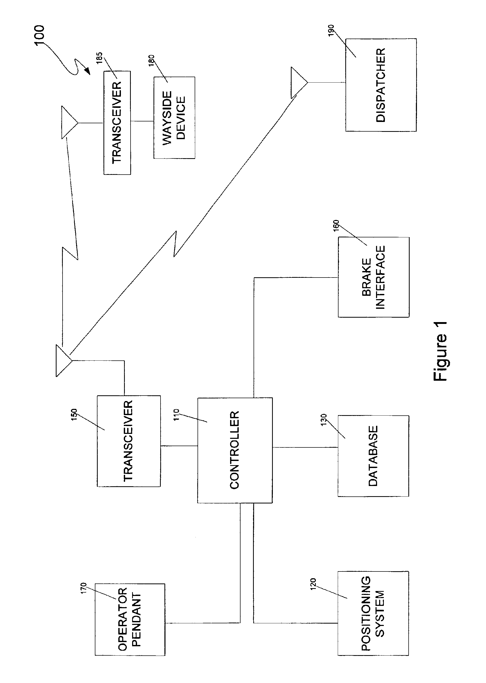
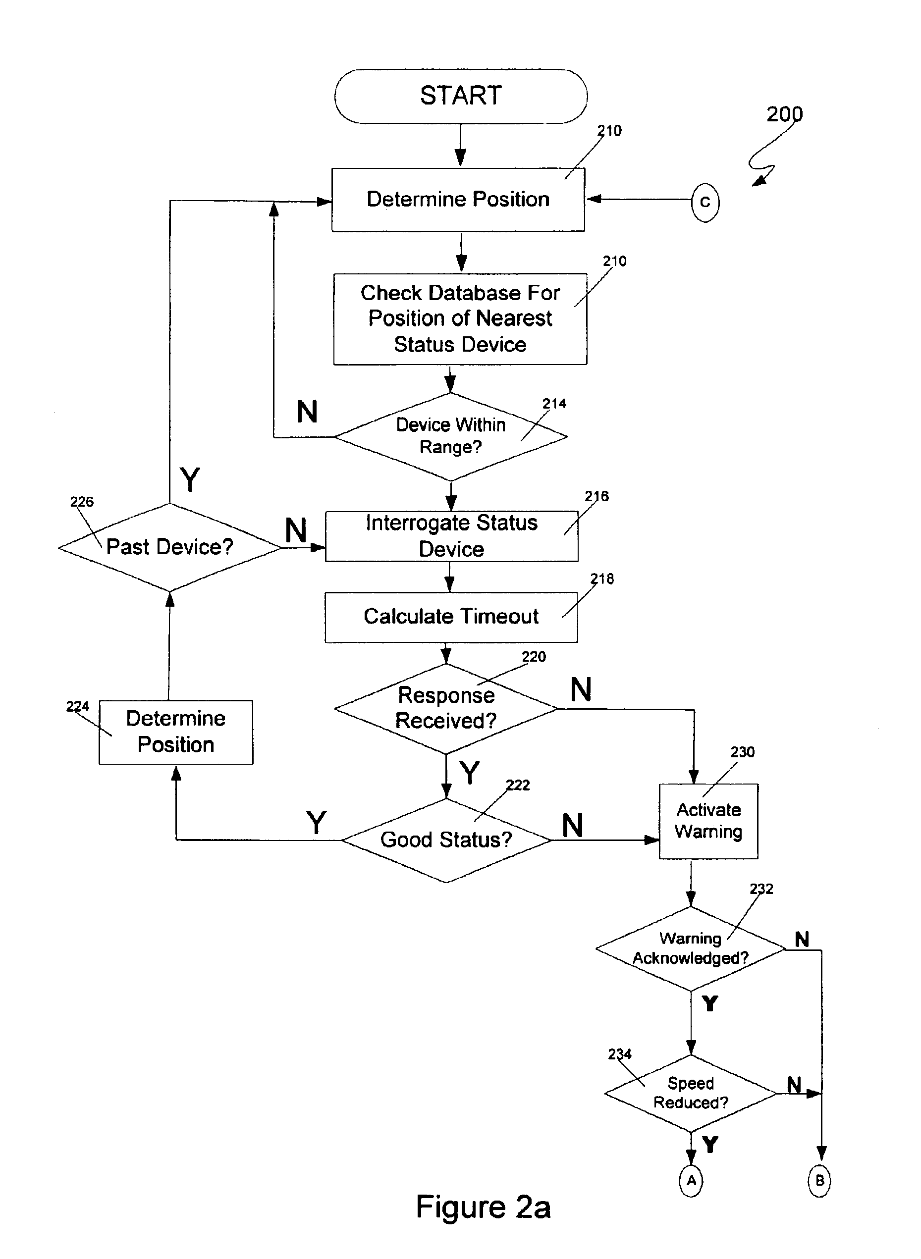
Referring now to the drawings, wherein like reference numerals designate identical or corresponding parts throughout the several views, FIG. 1 is a logical block diagram of a train control system 100 according to an embodiment of the present invention. The system 100 includes a control module 110, which typically, but not necessarily, includes a microprocessor. The control module 110 is responsible for controlling the other components of the sys...


PUM


Abstract

An automated fault reporting system for a train includes a controller that gathers information concerning malfunctioning wayside status devices and automatically reports the information to an appropriate party. In one embodiment, the control module uses a positioning system and a database including device locations in order to determine when the train is near a device. If no status information is received from the device as the train approaches, or the status information indicates a problem, the train is allowed to continue at a reduced speed to allow the operator to visually confirm that it is safe to proceed. If an area monitored by the device has been passed, or if the operator indicates that there is no problem, or the device fails to respond, the controller records and reports the malfunction.

Description

BACKGROUND OF THE INVENTION1. Field of the InventionThe invention relates to railroads generally, and more particularly to a method and system for automatically reporting faults in wayside devices.2. Discussion of the BackgroundTrain safety has long been a concern in the railroad industry. This concern has led to proposals for and development of automated, safety-enhancing systems including Cab Signaling Systems, Automatic Train Control Systems (ATC), and a Positive Train Control (PTC) System known as the TRAIN SENTINEL™ system available from the assignee of the present application, Quantum Engineering, Inc.These automatic systems vary in their implementation. However, one aspect shared by several of these systems is the use of wayside devices that electronically transmit status information to either a train or a centralized train control authority such as a dispatcher. In some systems, the devices transmit the status information upon receiving an interrogation signal from an approa...

Claims


Application Information

Patent Timeline
Patent Type & Authority Patents(United States)
IPC IPC(8): B61L1/20B61L1/00B61L27/00
CPCB61L1/20B61L27/0088B61L2205/04B61L27/53
Inventor KANE, MARK EDWARDSHOCKLEY, JAMES FRANCISHICKENLOOPER, HARRISON THOMAS
Owner SIEMENS MOBILITY INC
Why Eureka
Try Eureka