
Self-laminating strip label and method for assembling same

Inactive Publication Date: 2005-03-08
LASERBAND LLC
View PDF38 Cites 87 Cited by
  • Summary
  • Abstract
  • Description
  • Claims
  • Application Information

AI Technical Summary

Problems solved by technology

One such issue has been the unevenness with which these strip labels have been applied to the folders, thereby interfering with the eyeballing of a row of files to locate files that are out of place and otherwise making it difficult to locate a particular file due to the inconsistent appearance of the file labels.
As it is desired for files to be kept neat and organized, an inconsistent appearance detracts from that goal.
Still another issue which has arisen through the use of these types of labels is the propensity for the customized labeling to be worn away by the constant handling of the file by the strip label, which covers the file tab.
This usage induces an inordinate amount of wear on the pre-printed color bars or bar code or other identifying indicia as a person's fingers have contaminants such as perspiration, hand lotion, and other such substances which contact the face of the label and have a deleterious affect thereon.
Furthermore, in some instances, the file may be difficult to remove or replace due to the crowding of the file folders so that some appreciable gripping force is applied, and the users fingers may slip, thereby “smearing” the label as the user attempts to move the file.
However, that alignment issue is only addressed in the context of the aforementioned foil sheet having multiple strip labels and separate full sheet having multiple matching laminating strips.
As the lamination material would generally require a lamination carrier, and lamination material is relatively expensive, this solution does represent a significant additional expense.
Furthermore, separate sheets of strip labels and laminating strips have to be handled by a staff person in order to assemble the strip labels, which takes time and effort.
Unless proper care is taken, it is entirely possible and even likely that the laminating strips will not be properly aligned thereby detracting from the desired overall neatness of appearance, not even considering that improperly aligned laminating strips could result in premature peeling of the strip label / laminating strip from the file tab and thus failure of the strip label.

Method used


Image

  • Self-laminating strip label and method for assembling same
  • Self-laminating strip label and method for assembling same
  • Self-laminating strip label and method for assembling same

Examples


second embodiment

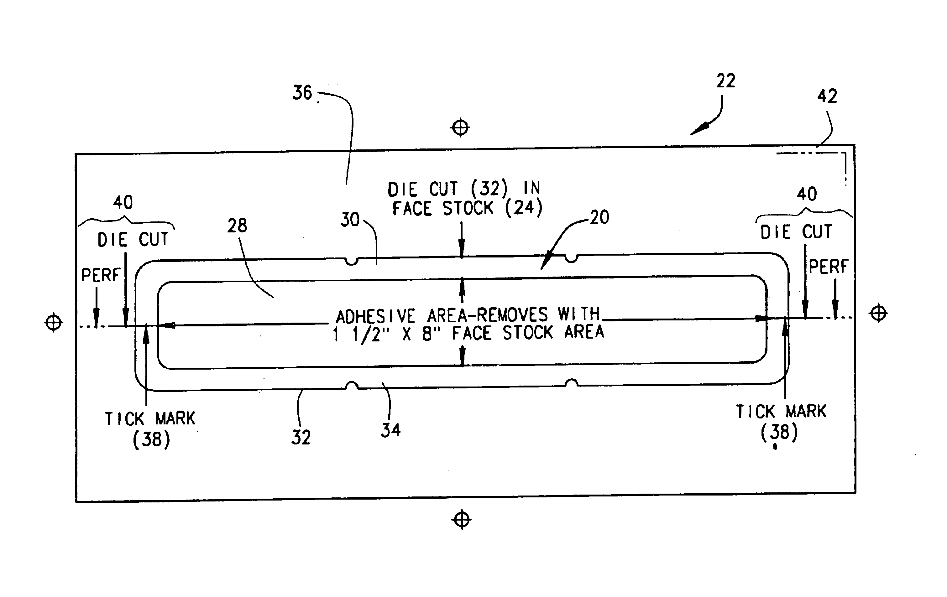
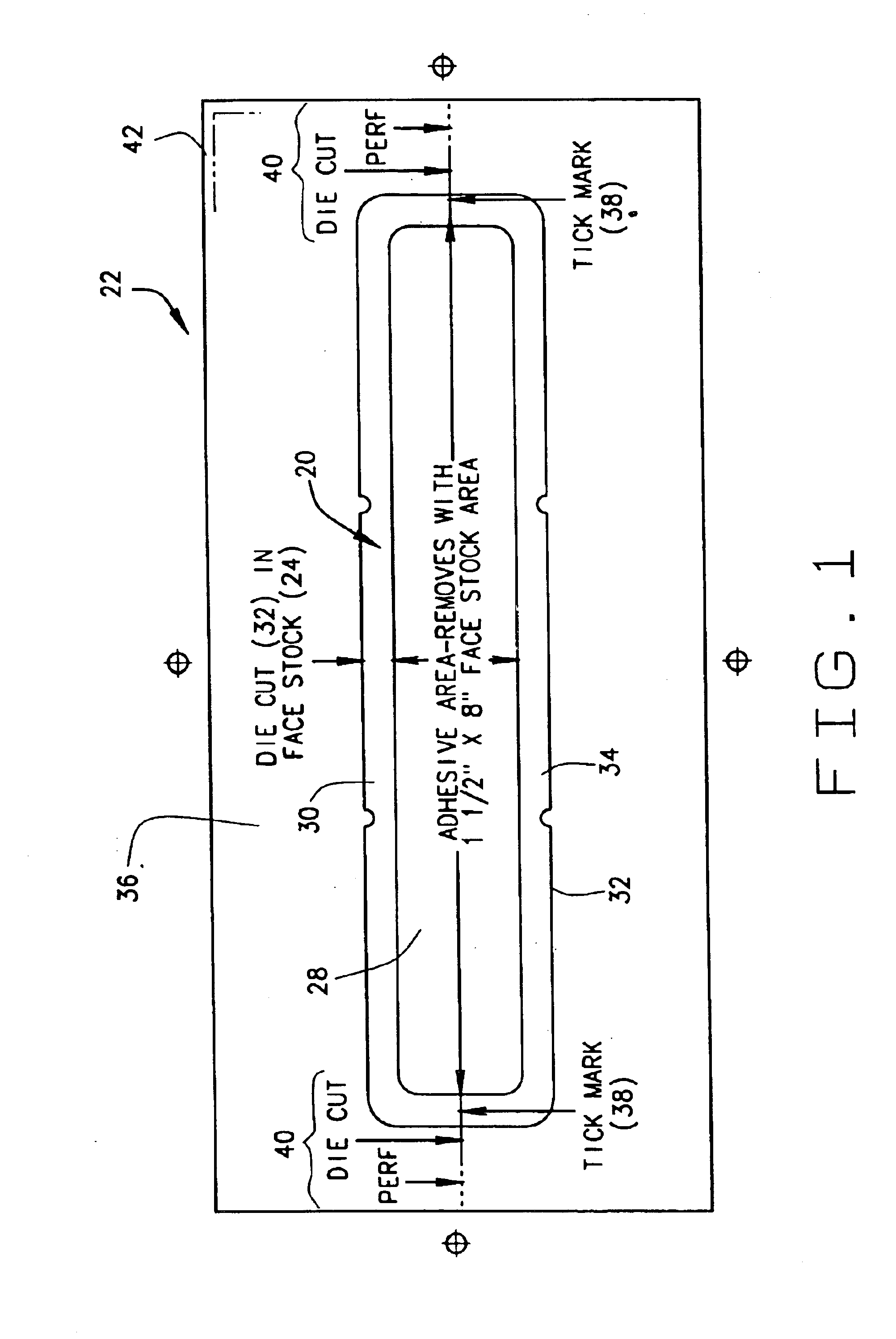
FIG. 4 is a top view of the present invention detailing the die cuts for both the dummy label and strip label in the face stock layer;

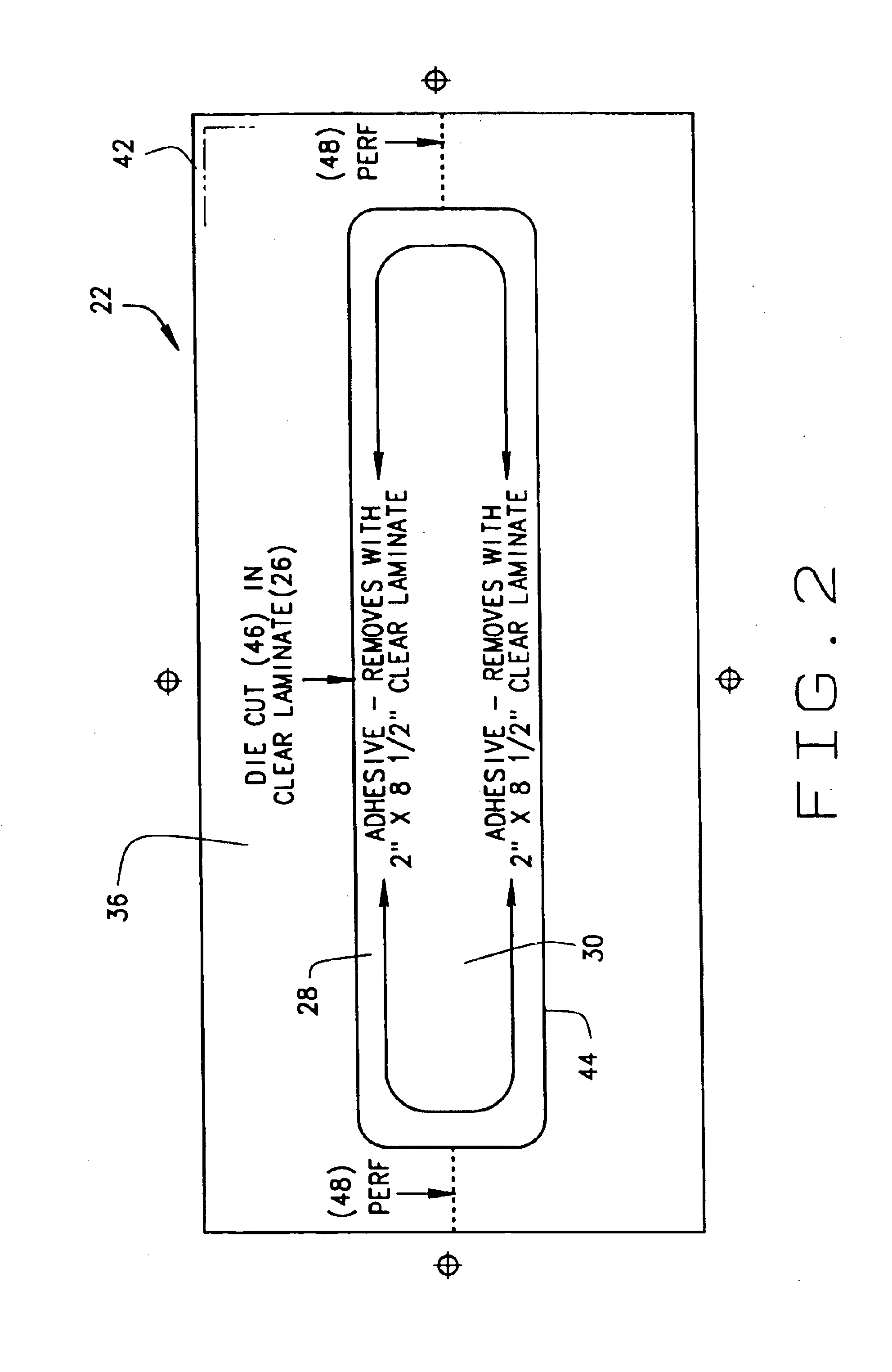
FIG. 5 is a bottom view of the second embodiment detailing the die cut in the lamination for forming the lamination strip;

third embodiment

FIG. 6 is a top view of the third embodiment detailing the face stock layer and corresponding separation lines for forming the strip label;

FIG. 7 is a bottom view of the third embodiment detailing the separation lines for forming the lamination;

first embodiment

FIG. 8 is a bottom view of the matrix formed from the first embodiment;

FIG. 9 is a bottom view of the matrix formed from the second embodiment; and

FIG. 10 is a bottom view of the matrix formed from the third embodiment.


PUM


Abstract

A business form is provided comprising two layers of material. A first of the layers comprises a strip label layer and a second of the layers comprises a lamination layer. The strip label layer has a separation line therein defining a strip label and the lamination layer has a separation line therein defining a lamination. The layers are separated by a patterned adhesive layer so that the strip label and the lamination may be removed from the form and adhered with the patterned adhesive to another business form with the lamination overlying the strip layer to protect same.

Description

BACKGROUND OF THE INVENTIONIt is well know in the art that labels are useful for many types of business forms. In many applications, it has been found that it is much more cost effective and convenient to provide essentially blank forms and then some form of separate customizable or printable label for uniquely identifying that form. One such major application for this technique includes the typical file folder with which those in office settings are imminently familiar. There are many different types of file folders including the ubiquitous manila file folders that have a tab which in the prior art provides a convenient place for the application of a label or even hand scrawling an identifying title for its contents. This tab has been located at the top or side of the file folder to accommodate the particular filing cabinet or shelf used to store what is typically a series of them each holding related information, such as patient files, customer files, etc. As an aid in maintaining...

Claims


Application Information

Patent Timeline
IPC IPC(8): G09F3/02
CPCG09F3/0288Y10T428/14Y10T428/15Y10T428/1495
Inventor RILEY, JAMES M.
Owner LASERBAND LLC
Learn More