Automatic dimming mirror using semiconductor glare sensor

a technology of glare sensor and dimming mirror, which is applied in the direction of photometry using electric radiation detectors, optical radiation measurement, instruments, etc., can solve the problems of glare experienced before the mirror could be switched, temporary visual impairment or dazzle the operator, and general worsening of problems

Inactive Publication Date: 2005-03-08
GENTEX CORP
View PDF43 Cites 21 Cited by
  • Summary
  • Abstract
  • Description
  • Claims
  • Application Information

AI Technical Summary

Benefits of technology

It is an object of the present invention to provide an automatically dimming mirror capable of operating over a wide range of lighting conditions.
Still another object of the present invention is to provide an automatically dimming mirror with less susceptibility to temperature variations.
Yet another object of the present invention is to provide an automatically dimming mirror that is inexpensive to produce.
A further object of the present invention is to provide an automotive rearview mirror system with improved exterior mirror performance.
In an additional embodiment of the present invention, a glare lens is provided for the glare sensor. The glare lens provides the glare sensor with a narrower field of view and a higher optical gain than the ambient light sensor.

Problems solved by technology

Bright lights appearing in a scene behind the vehicle, such as from another vehicle approaching from the rear, may create glare in a rearview mirror that can temporarily visually impair or dazzle the operator.
This problem is generally worsened during conditions of low ambient light such as occur at night, when the eyes of the vehicle operator have adjusted to the darkness.
Difficulties with manually controlled mirrors include the glare experienced before the mirror could be switched as well as operator distraction caused by finding and operating the mirror control.
This design proved to be inadequate since the threshold perceived by the operator for dimming the mirror, known as the glare threshold, varied as a function of the ambient light level.
The cost of the imaging array, the required lens, and complicated signal processing logic make the use of an imaging array prohibitively expensive for many automotive applications.
Also, light collected from a side view less accurately represents the ambient light experienced by the vehicle operator than does light from a forward view.
If a sensor is to be mounted in an outside mirror, even harsher operating conditions can be expected.
Disadvantages with CdS cells include a high degree of variance between cells, slow response at low light levels, poor environmental stability, and difficulty being assembled by automated electronic manufacturing equipment.
However, the bridge output represents a fixed relationship between ambient light and glare that is often not appropriate throughout the range of ambient light levels.
However, photodiodes tend to be expensive and produce very low currents at low light levels.
These low currents require special amplification techniques to achieve a useful signal, increasing the cost of the automatic mirror.
One disadvantage of silicon-based light transducers is a frequency response different than that of the human eye.
One difficulty with all types of light sensors is the occurrence of operating anomalies at high temperatures.
Some devices become extremely non-linear at high temperatures.
Some devices, such as CdS cells, may suffer a permanent change in operating characteristics.
Devices may even provide completely false readings such as indicating bright light in low light conditions due to excessive thermal noise.

Method used


Image

  • Automatic dimming mirror using semiconductor glare sensor
  • Automatic dimming mirror using semiconductor glare sensor
  • Automatic dimming mirror using semiconductor glare sensor

Examples


Embodiment Construction

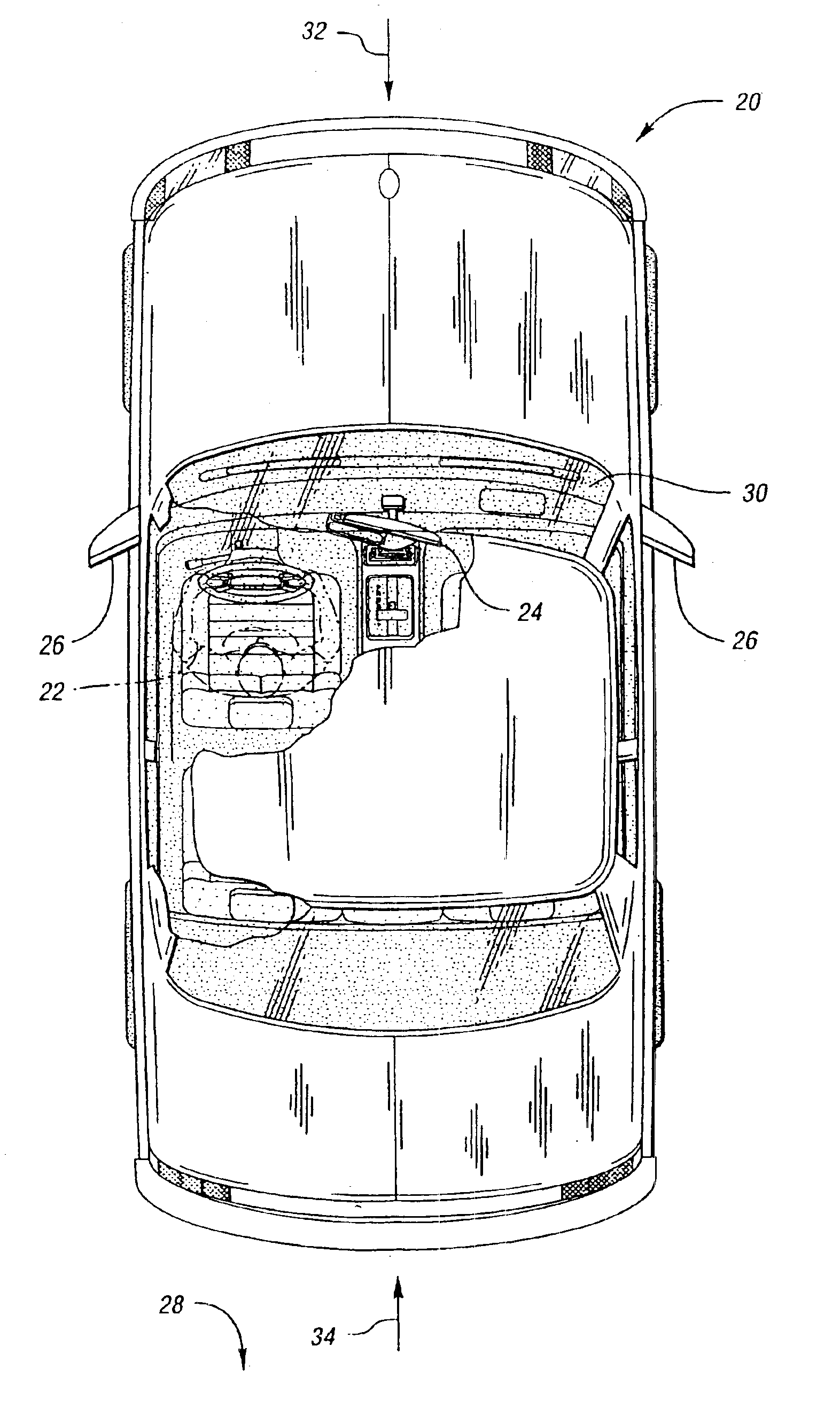
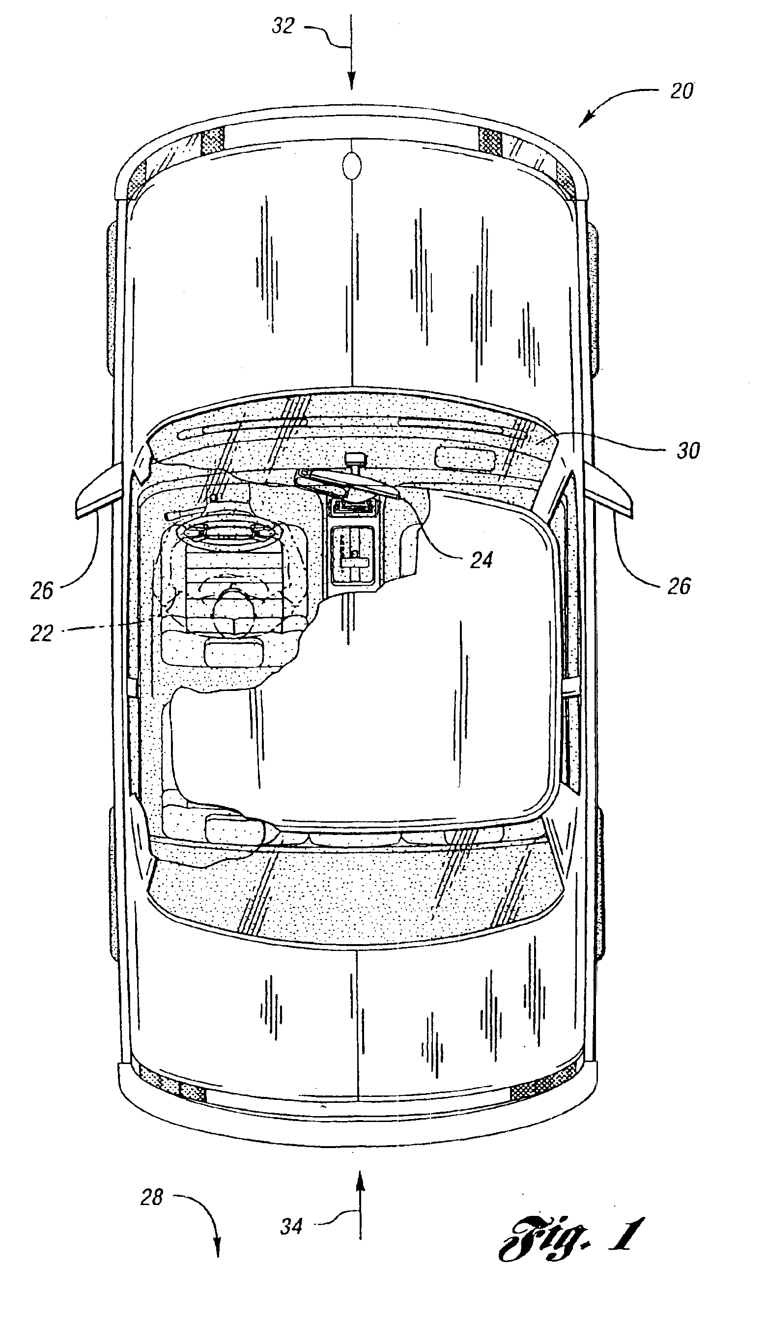
Referring now to FIG. 1, a drawing illustrating vehicle rearview mirrors that may incorporate the present invention is shown. Vehicle 20 is driven by operator 22. Operator 22 uses interior rearview mirror 24 and one or more exterior rearview mirrors 26 to view a rearward scene, shown generally by 28. Most of the time, operator 22 is looking forward through windshield 30. The eyes of operator 22 therefore adjust to ambient light 32 coming from a generally forward direction. A relatively bright light source in rearward scene 28 may produce light which can reflect from mirrors 24,26 to temporarily visually impair, distract, or dazzle operator 22. This relatively strong light is known as glare 34.

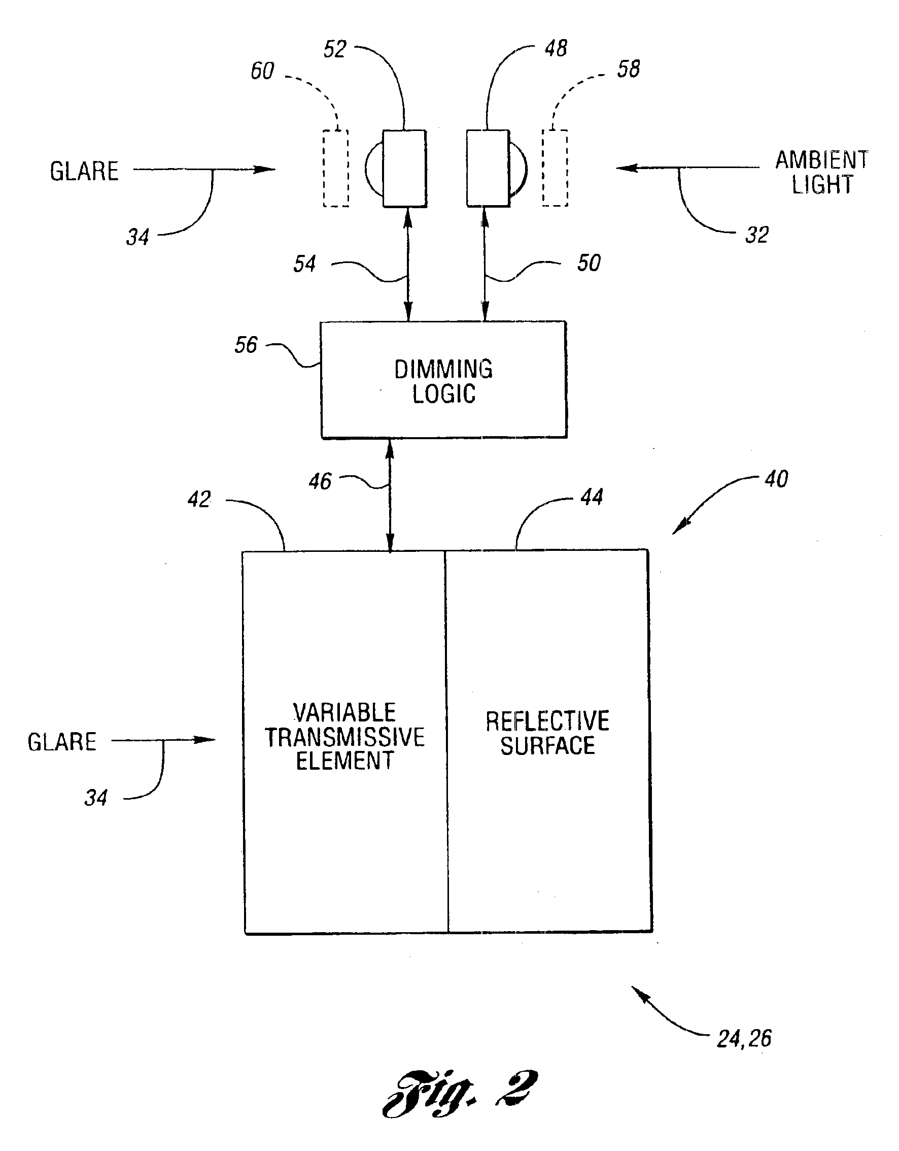
To reduce the impact of glare 34 on operator 22, the reflectance of mirrors 24,26 may be reduced. Prior to automatically dimming mirrors, interior rearview mirror 24 would contain a prismatic reflective element that could be manually switched by operator 22. Automatically dimming mirrors includ...


PUM


Abstract

An automatically dimming mirror includes a dimming element having variable reflectivity, the degree of reflectivity based on a control signal. An ambient light sensor is positioned to receive light from a region generally in front of the vehicle. The ambient light sensor outputs a discrete ambient light signal based on the amount of light incident on the ambient light sensor over an integration period. A glare sensor is positioned to view the scene generally behind the vehicle operator. The glare sensor outputs a discrete glare signal based on the amount of light incident on the glare sensor over an integration period. A dimming logic determines an ambient light level based on the ambient light signal. The glare integration period is determined based on the ambient light level. The glare signal resulting from the glare integration period determines a mirror glare level used to set the dimming element control signal.

Description

TECHNICAL FIELDThe present invention relates to automotive rearview mirrors that automatically dim in response to glare.BACKGROUND ARTVehicle operators use interior and exterior rearview mirrors to view scenes behind the vehicle without having to face in a rearward direction and to view areas around the vehicle that would otherwise be blocked by vehicle structures. As such, rearview mirrors are an important source of information to the vehicle operator. Bright lights appearing in a scene behind the vehicle, such as from another vehicle approaching from the rear, may create glare in a rearview mirror that can temporarily visually impair or dazzle the operator. This problem is generally worsened during conditions of low ambient light such as occur at night, when the eyes of the vehicle operator have adjusted to the darkness.Various solutions have evolved to deal with the problem of glare in automotive rearview mirrors. Initially, a prismatic mirror was provided that could be manually ...

Claims


Application Information

Patent Timeline
Patent Type & Authority Patents(United States)
IPC IPC(8): B60R1/08G01J1/46
CPCB60R1/088G01J1/46G01J1/4204
Inventor BECHTEL, JON H.STAM, JOSEPH S.TURNBULL, ROBERT R.NIXON, ROBERT H.FOSSUM, ERIC R.
Owner GENTEX CORP
Why Eureka
Try Eureka