
Ergonomic controls in a surgical lighting system

a lighting system and ergonomic technology, applied in the field of ergonomic controls in surgical lighting systems, can solve the problems of difficult sterilization for subsequent procedures, consume both the nurse's time and the surgeon's attention, and achieve the effect of convenient access

Inactive Publication Date: 2005-03-08
AMERICAN STERILIZER CO
View PDF30 Cites 36 Cited by
  • Summary
  • Abstract
  • Description
  • Claims
  • Application Information

AI Technical Summary

Benefits of technology

The present invention provides a lighting system with a lighthead that includes a housing, a light source, and a bezel with lighting control input means for adjusting the intensity of light emitted by the light source. The invention also provides a surgical light apparatus with a housing, a light source, a handle, a bezel area, and a controller for controlling various functions. The invention also includes a method of adjusting illumination from a lighthead by covering the handle with a sterile cover and manipulating it to adjust the pattern size and intensity of the illuminated light. The technical effects of the invention include easy access to light intensity control, improved control of lighting patterns, and the ability to adjust intensity without disconnecting mechanical or electrical connections between the intensity control switches and the light source.

Problems solved by technology

This consumes both the nurse's time, and the surgeon's attention.
A primary disadvantage of this system, however, is that it is very awkward to use.
Additionally, the push-button mechanism creates surfaces where blood can become lodged, making sterilization for subsequent procedures difficult.
Still further, functionally, the single push button allows only unidirectional light level cycling.

Method used


Image

  • Ergonomic controls in a surgical lighting system
  • Ergonomic controls in a surgical lighting system
  • Ergonomic controls in a surgical lighting system

Examples


Embodiment Construction

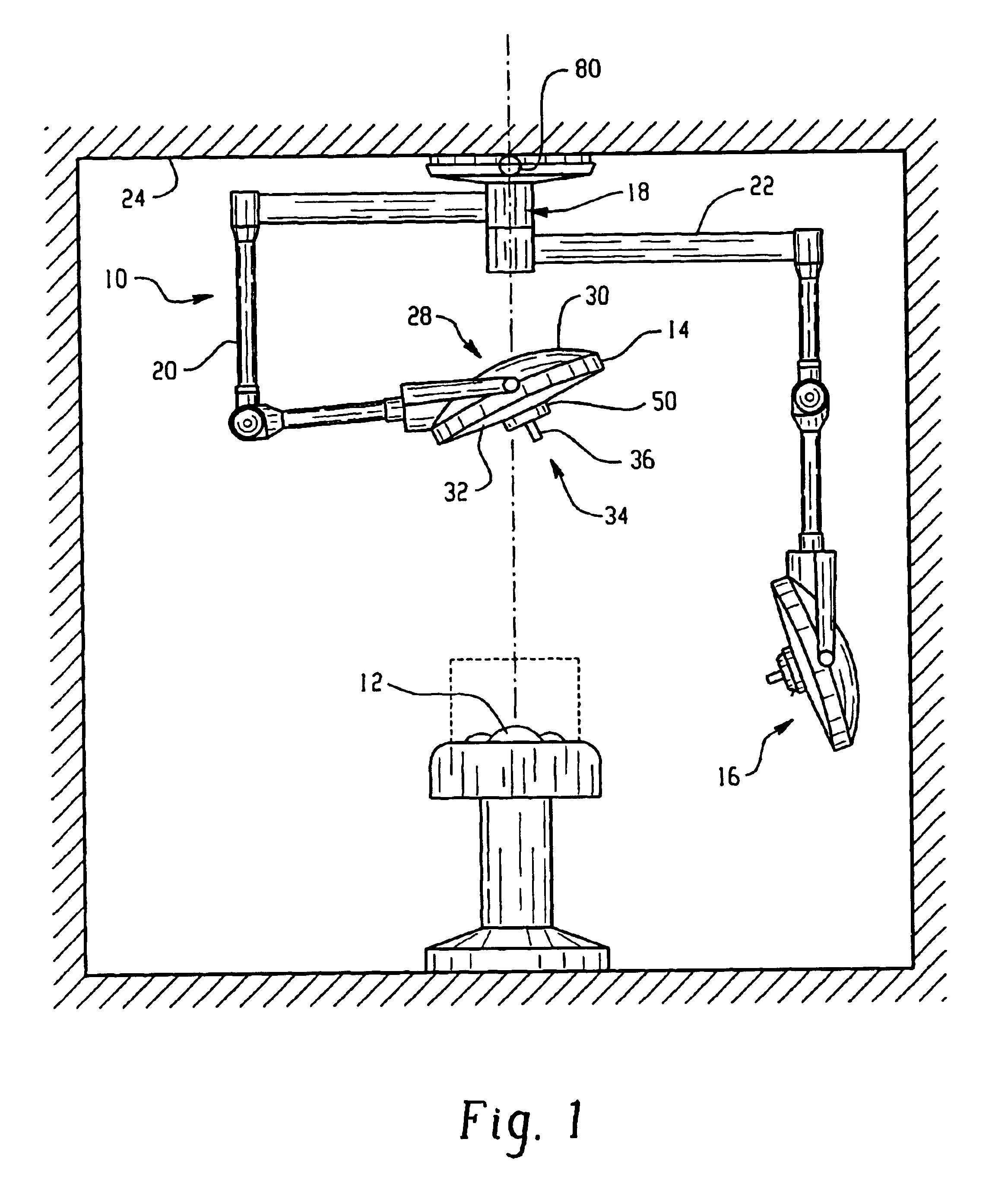
With reference to FIG. 1, an overhead lighting system 10 suited to use in an operating room illuminates areas of a patient 12 undergoing surgery. The system 10 illustrated in FIG. 1 includes two lightheads 14, 16, which are suspended from a common mounting system 18 by articulated arm assemblies 20, 22, respectively. The arm assemblies allow the lightheads to be independently movable to a variety of positions relative to a ceiling 24 and the patient. The lighting system 10 is rigidly mounted to a suitable stationary support, such as a beam (not shown), typically located above the ceiling. As will be appreciated, the lighting system 10 may also include other medical devices, such as task lights, monitors, cameras, and the like (not shown).

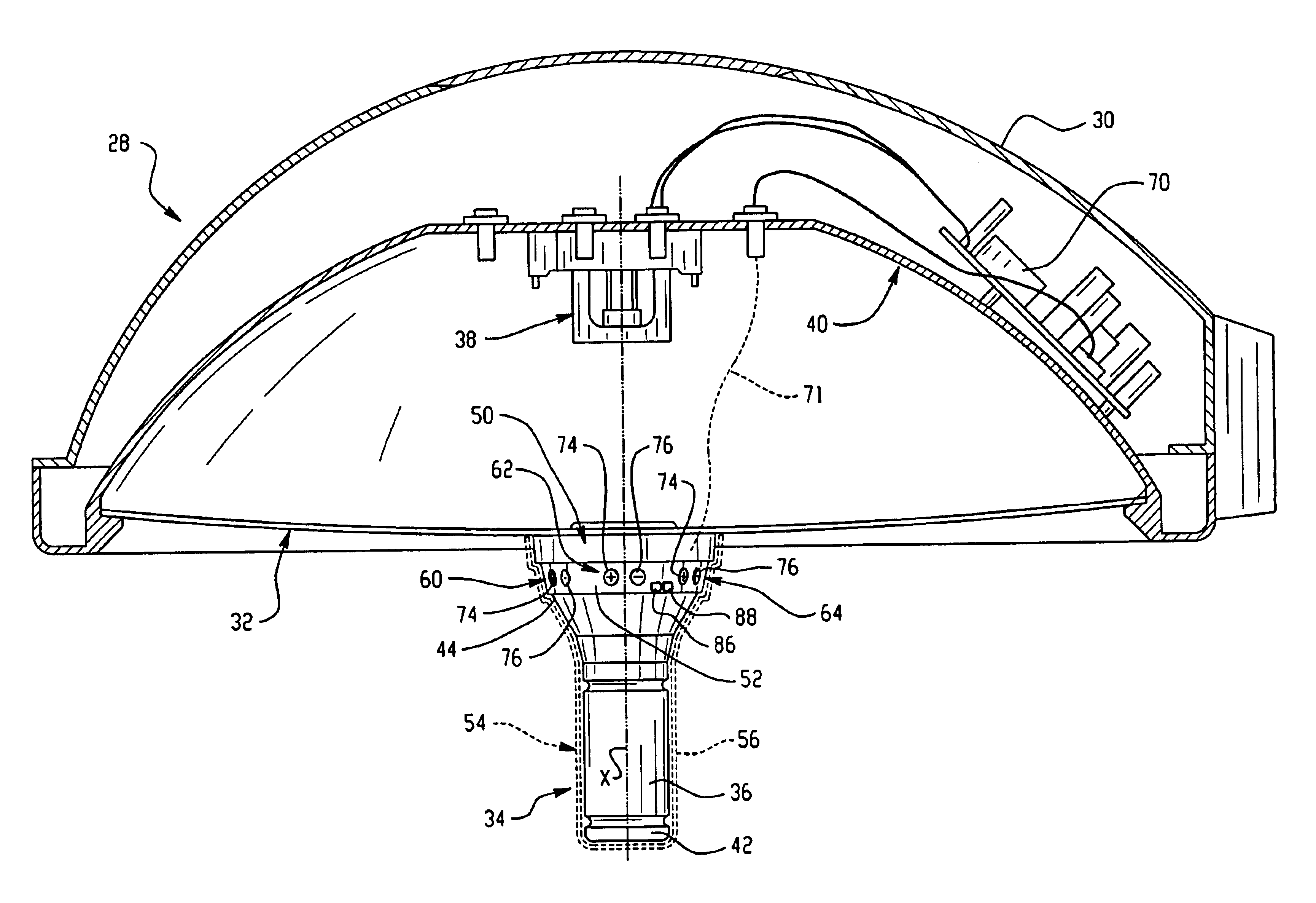
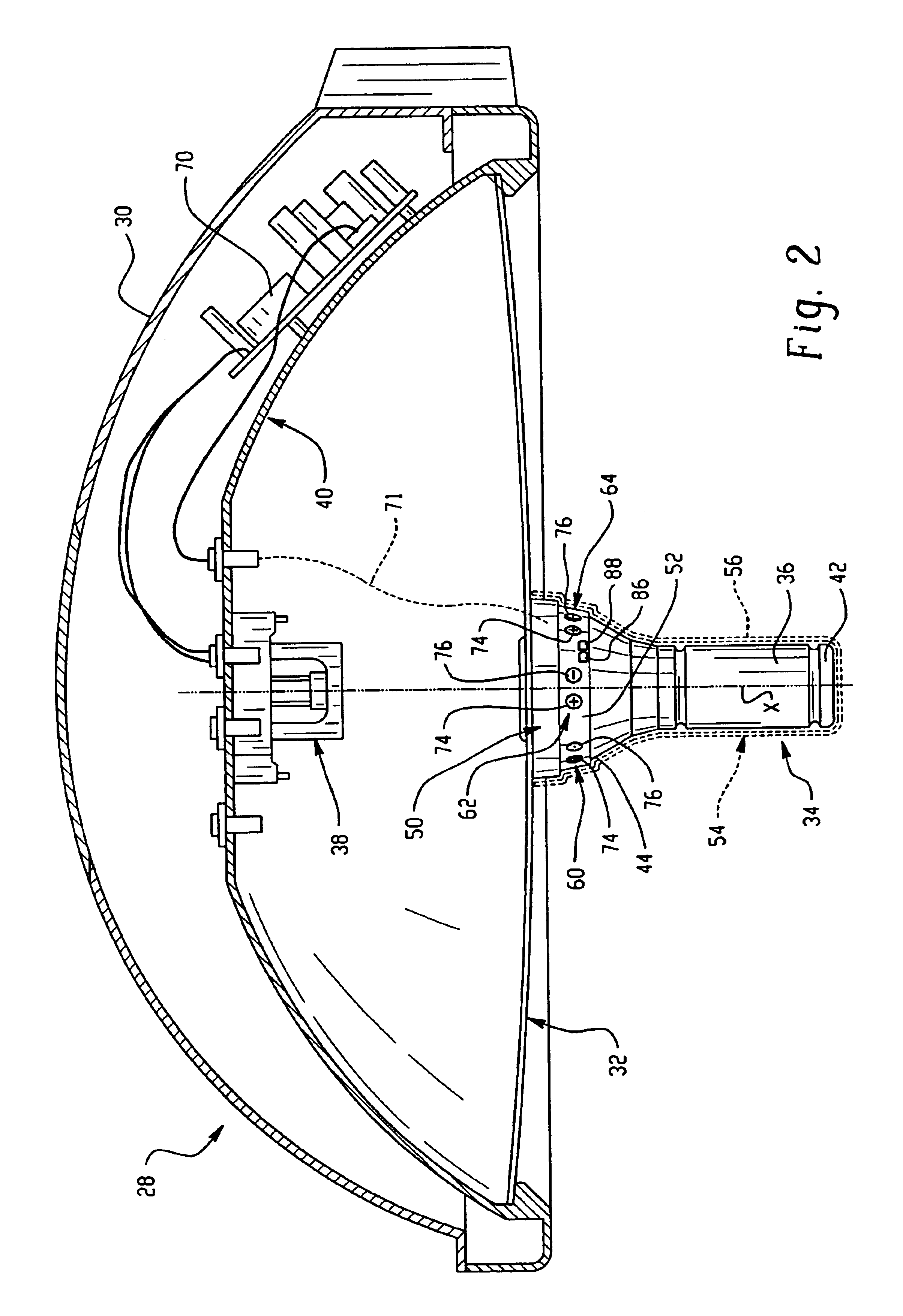
Each lighthead 14, 16 includes a housing 28 including a dome-shaped cover or shell 30, a lens system 32, through which the light shines from the respective lighthead, and a handle assembly 34, shown in detail in FIGS. 2 and 3. To maneuver a lighthea...


PUM


Abstract

A lighting system (10) suited to use in an operating theater includes one or more lightheads, each having a housing (28) and a bezel (50) extending therefrom. A light source (38) is disposed within the housing. A handle (36) extends below the bezel and is rotatable relative thereto. A lighting control input means (60), associated with the bezel allows adjustment of the intensity of light emitted by the light source. A sterile cover (54) can be placed over both the handle and the bevel, allowing the input means to be manipulated by pressure on the cover with the thumb of the operator's hand, while simultaneously grasping the handle in the palm and fingers.

Description

BACKGROUND OF THE INVENTIONThe present invention relates to the surgical lighting and accessory control arts. It finds particular application in conjunction with controlling the intensity of light emanating from lightheads in an operating room (OR) setting and will be described with particular reference thereto. It is to be appreciated, however, that the invention also finds application in conjunction with controlling functions of other devices and is not limited to the aforementioned lighting application.Typically, in an operating room setting, large, high lumen output lightheads are used to illuminate the surgical site. At certain times during an operation, it is appropriate for the surgeon to adjust the intensity of the light. For example, the surgeon may prefer a more intense overhead light to illuminate the operating region better, or the surgeon may desire to decrease the strength of the overhead light to reduce the effects of shadows or glare. In some situations, the overhead...

Claims


Application Information

Patent Timeline
Patent Type & Authority Patents(United States)
IPC IPC(8): F21S8/00F21V21/40A61B90/30
CPCF21V21/403Y10S362/804F21W2131/205F21W2131/202F21S8/00F21V21/40
Inventor JESURUN, DAVIDGRESZLER, ALLAN J.KESELMAN, YURYDRABINSKI, TERRY A.RUS, STEVEN H.
Owner AMERICAN STERILIZER CO
Learn More