

Optical link device
- Summary
- Abstract
- Description
- Claims
- Application Information
AI Technical Summary
Benefits of technology
Problems solved by technology
Method used
Image

Examples
first embodiment
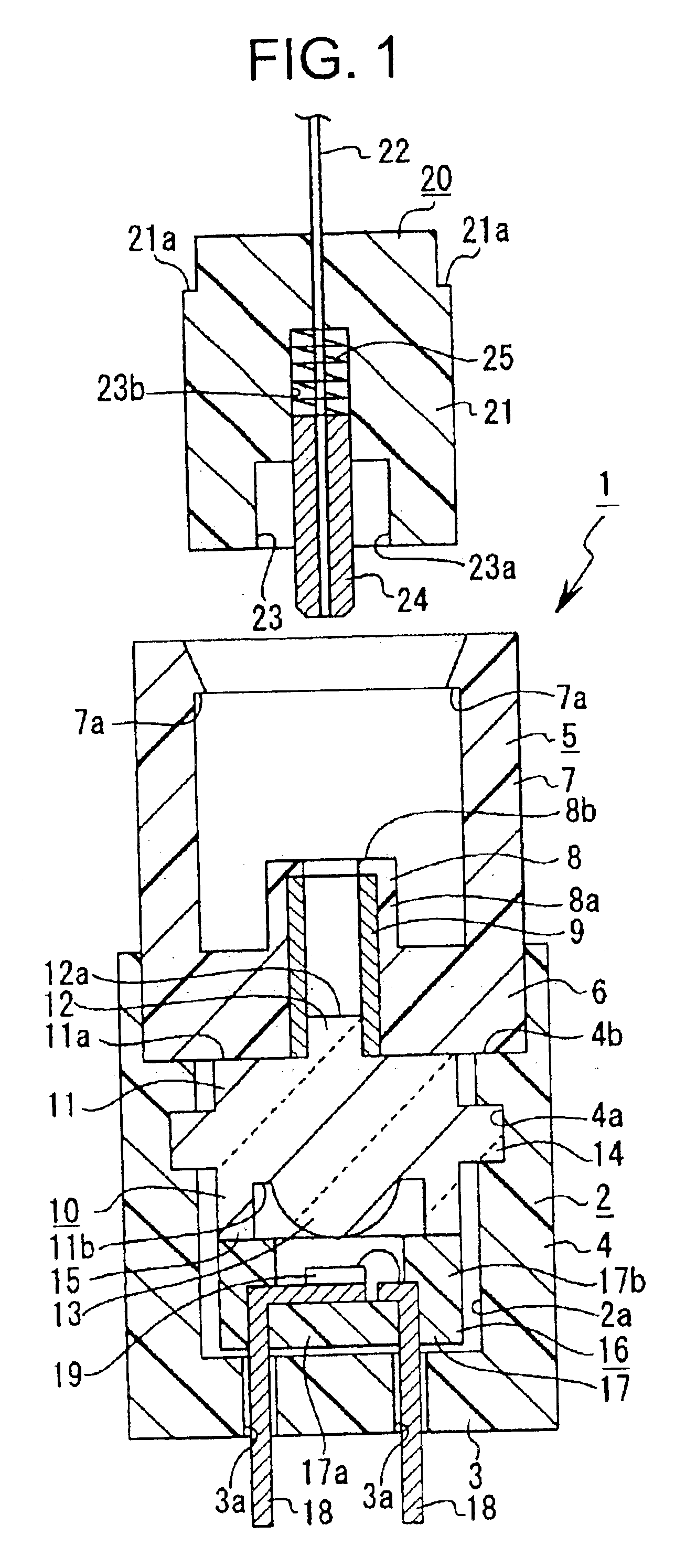
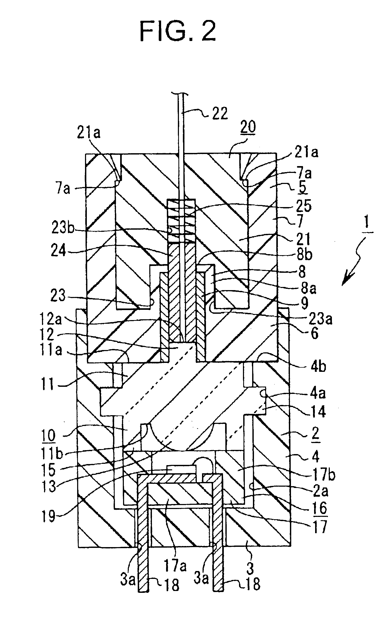
The first embodiment will be described with reference to FIG. 1 through FIG. 13.
An optical link device 1 includes a housing 2. The housing 2 is formed with a resin material and includes a bottom section 3 and a circumferential wall section 4, which is provided so as to stand at the circumferential edge of the bottom section 3, as shown in FIG. 1 and FIG. 2. The housing 2 includes two separate halves, which are joined together, and an internal space 2a is formed therein.
The bottom section 3 has a plurality of insertion holes 3a, 3a.
An attachment groove 4a is formed on the inner surface of the circumferential wall section 4 towards the upper part of the circumferential wall section 4 and extends in the direction of the circumference. A fitting concave section 4b is formed at the tip portion of the circumferential wall section 4 and extends in the direction of the circumference.
A receptacle 5 is coupled with the housing 2. The receptacle 5 is formed with a resin material and includes ...
fifth embodiment
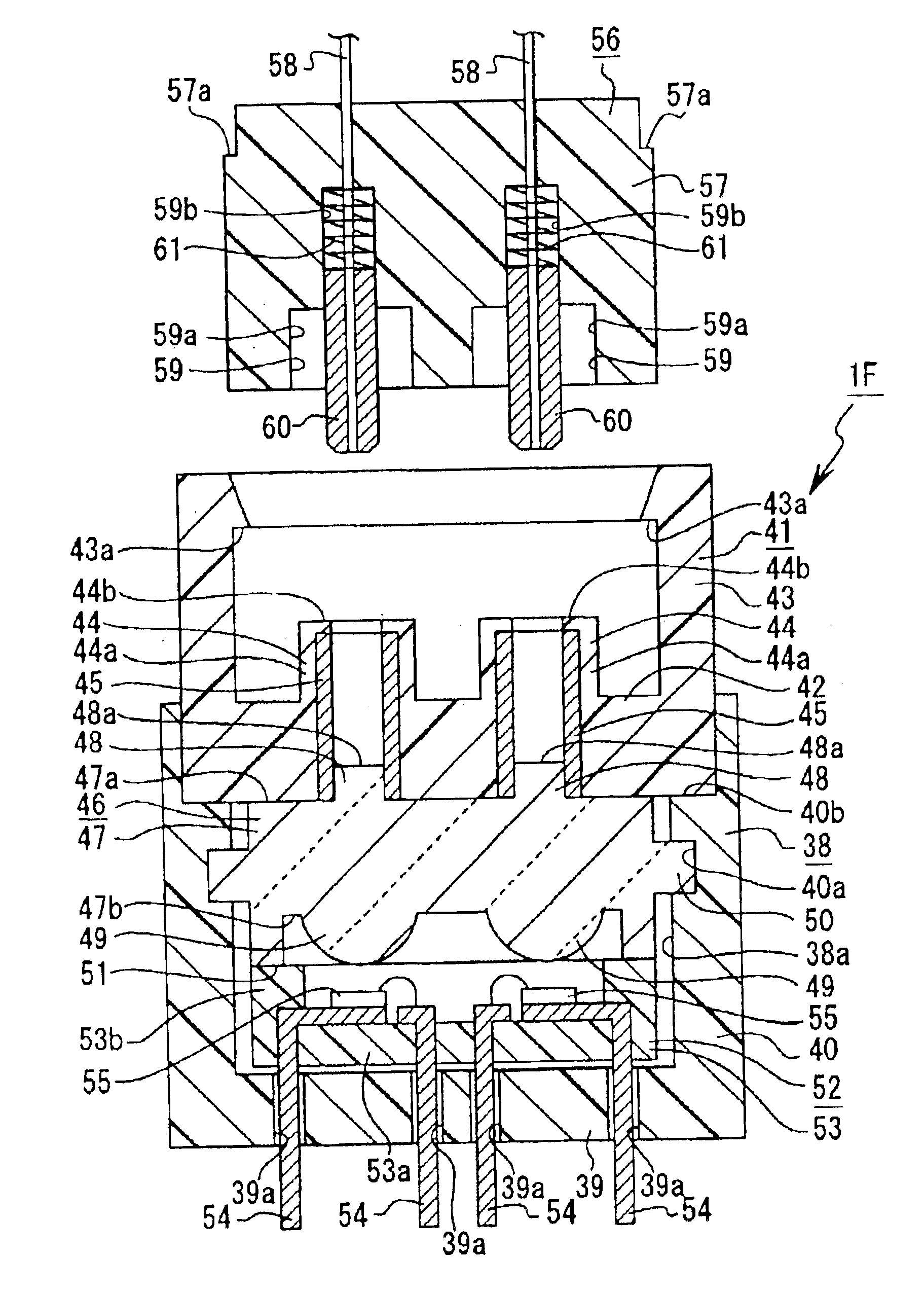
A fifth embodiment will be described next with reference to FIG. 19.
An optical link device 1F of the fifth embodiment is one in which the functions of the optical link device 1 of the first embodiment are expanded, and functions both as a receiver and a transmitter.
The optical link device 1F includes a housing 38, which is formed with a resin material and includes a bottom section 39 and a circumferential wall section 40 provided so as to stand on the circumferential edge of the bottom section 39. The housing 38 includes two separate halves that are joined together and the interior is formed as an internal space 38a.
A plurality of insertion holes 39a, 39a . . . are formed on the bottom section 39.
An attachment groove 40a is formed towards the tip of the inner side of the circumferential wall section 40 and extends in the direction of the circumference. A fitting concave section 40b is formed at the tip portion of the circumferential wall section 40 and extends in the direction of t...
seventh embodiment
A seventh embodiment will be described next with reference to FIG. 22.
An optical link device 1I of the seventh embodiment differs from the optical link device 1F of the fifth embodiment only in that the receptacle and the sleeve are formed in a single unit. Therefore, only the parts that differ from the optical link device 1F will be described in detail, while the other parts will be assigned the same reference numerals as those of the corresponding parts in the optical link device 1F and description thereof will herein be omitted.
The optical link device 1I of the seventh embodiment is one in which the features of the optical link device 1C of the third embodiment are expanded, and is equipped with functions of both a receiver and a transmitter.
In the optical link device 1I, a receptacle 41I and sleeves 45I, 45I are formed with a resin material and are unitized as a sleeve-integrated receptacle 69. For this reason, the optical link device 1I does not include a sleeve holder.
The inne...
PUM
 Abstract
Description
Claims
Application Information