
Wheel chock mounting plate assembly

a technology of mounting plate and wheel chock, which is applied in the direction of braking system, transportation and packaging, transportation items, etc., can solve the problems of hardware, including one or more mounting plates, still being fixed to the surface of the trailer, etc., and achieve the effect of convenient attachment and removal

Inactive Publication Date: 2005-03-08
PINGEL ENTERPRISE
View PDF16 Cites 32 Cited by
  • Summary
  • Abstract
  • Description
  • Claims
  • Application Information

AI Technical Summary

Benefits of technology

"The invention is a mounting plate that can be easily attached and removed from a trailer or other transporting vehicle. It attaches to a logistic track that is fixed to the load surface. The mounting plate has a fitting that engages the logistic track and securely holds the plate in place. It also has a longitudinally slideable key that prevents the mounting plate from moving in a direction transverse to the logistic track. The front of the mounting plate has a fitting that engages the logistic track and secures the mounting plate assembly in the longitudinal direction of the logistic track. The invention allows for easy attachment and removal of a wheel chock to a transporting vehicle and ensures that only hardware left behind on the vehicle is the logistic track, which can be used for other purposes."

Problems solved by technology

However, there are two potential problems with this type of mounting.
First, the wheel chock is a relatively permanent fixture on the surface of the trailer impeding the use of the trailer for other purposes.
Second, the wheel chock may be removed but that usually entails the difficulty of removing screws or other fasteners, sometimes resulting in holes in the surface of the trailer, or leaving limited purpose hardware attached to the surface of the trailer.
However, the problem of hardware, including one or more mounting plates, remaining fixed to the surface of the trailer still exists.

Method used


Image

  • Wheel chock mounting plate assembly
  • Wheel chock mounting plate assembly
  • Wheel chock mounting plate assembly

Examples


Embodiment Construction

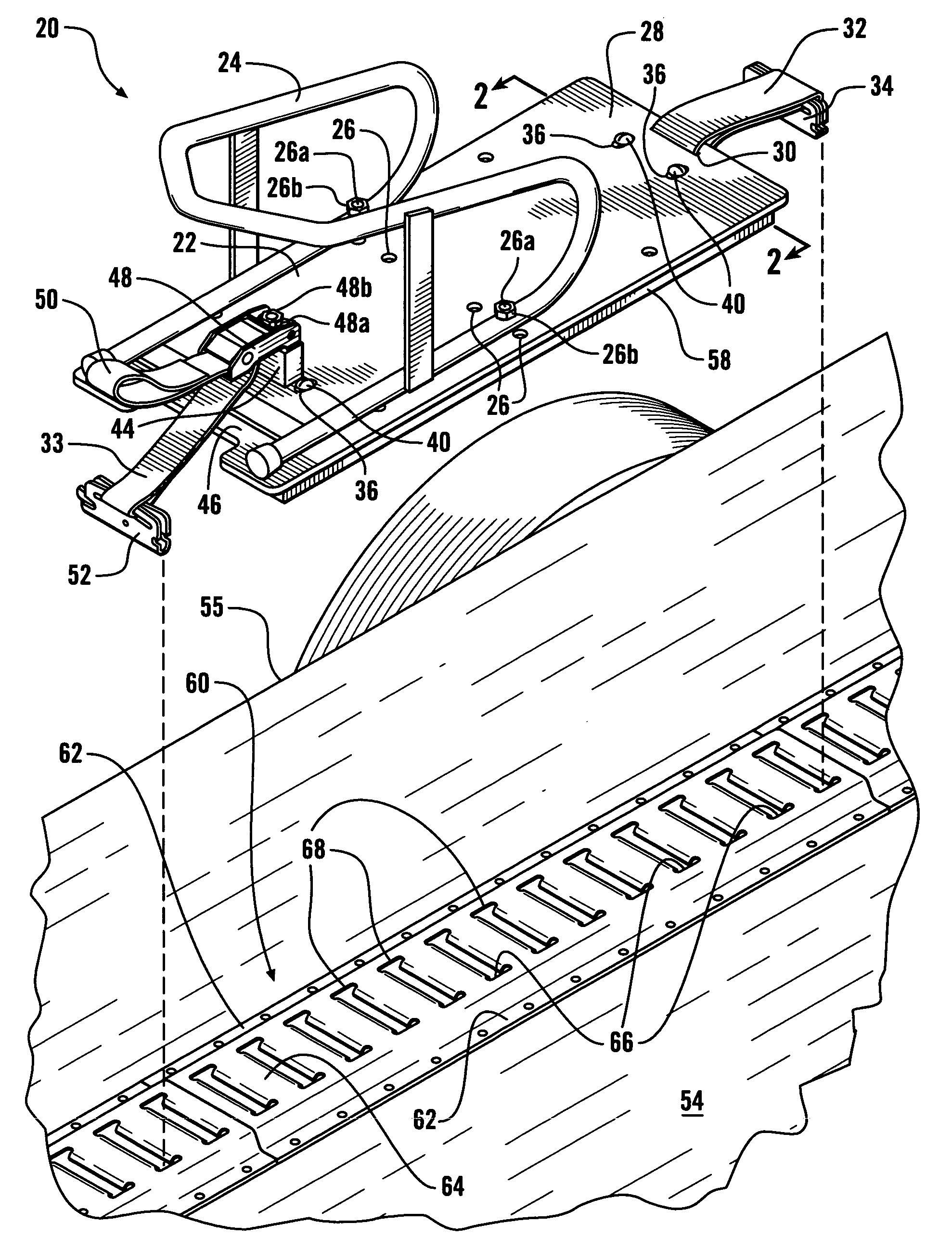
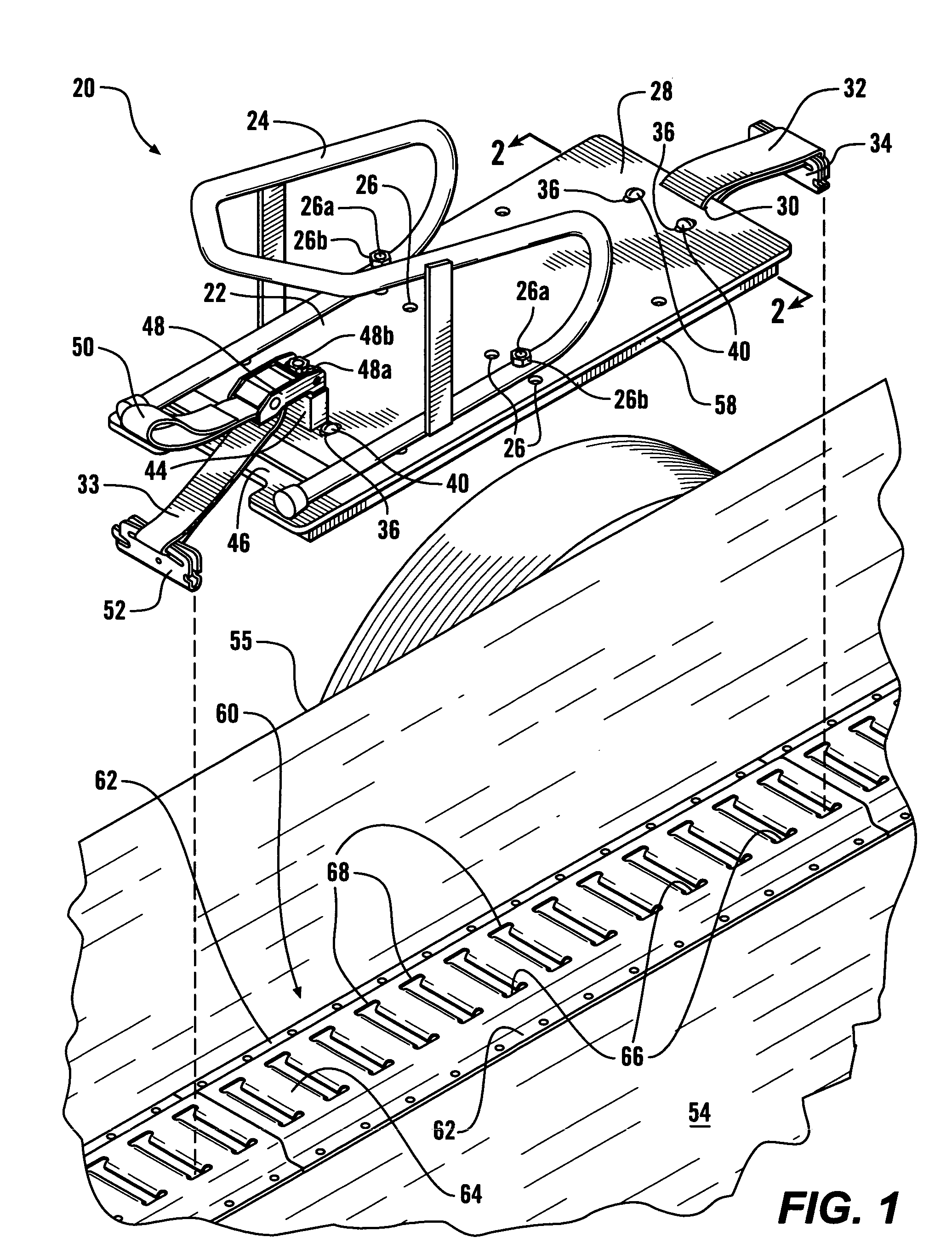
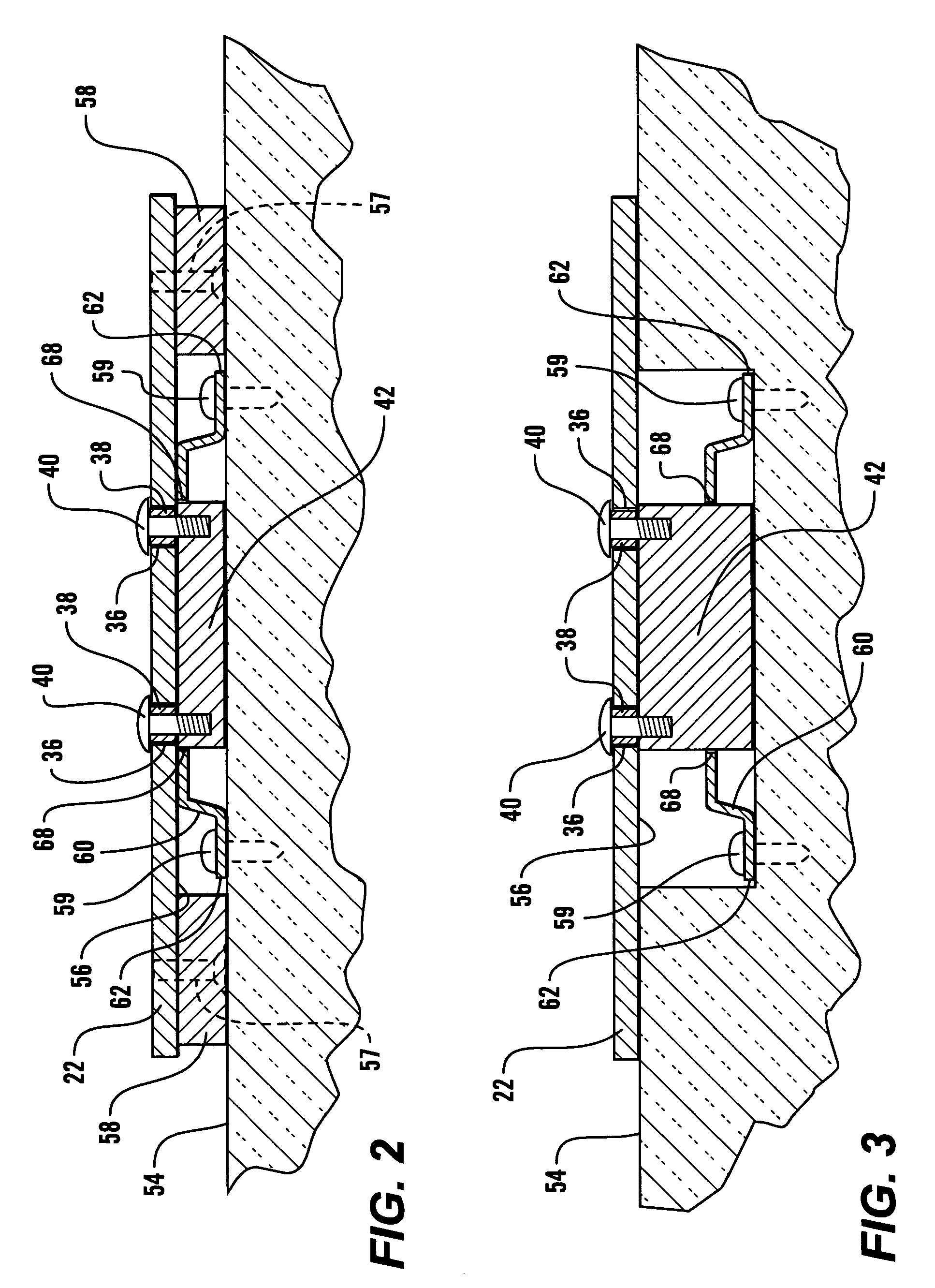
Referring more particularly to FIG. 1, there is shown a preferred embodiment of a wheel chock mounting plate assembly 20 in accordance with the present invention detached from a conventional Series E logistic track 60. The wheel chock mounting plate assembly 20 has a mounting plate 22. The mounting plate 22 is preferably precisely drilled and machined to receive a selected wheel chock 24, a device used to secure and restrain the wheel of a motorized vehicle. The mounting plate 22 preferably has several bolt holes 26 so that wheel chocks of differing shapes and sizes may be attached. The wheel chock 24 shown is one of a variety that may be bolted to the mounting plate 22. The bolt holes 26 are preferably countersunk in the bottom surface 56 of the mounting plate 22 so that flat head bolts or machine screws 26a and lock nuts 26b may preferably be used to secure the wheel chock 24 on the mounting plate 22.

The rear end 28 of the mounting plate 22 preferably has a slot 30 that runs in a...


PUM


Abstract

A wheel chock mounting plate assembly that can be easily attached to and removed from the load surface of a trailer or other transporting vehicle. The wheel chock mounting plate assembly attaches to a logistic track, standard in the field of cargo control systems, that is fixed to the load surface. The wheel chock mounting plate is precisely drilled and machined to receive a wheel chock. The mounting plate assembly has a fitting adapted to engage the logistic track attached with a logistic strap to the rear end of the mounting plate. At least one longitudinally slideable key is adapted to extend below the mounting plate to fit in a transverse opening of the logistic track to prevent the mounting plate from moving in a direction transverse to the length of the logistic track. The front of the mounting plate has a fitting adapted to engage the logistic track and secure the mounting plate assembly in the longitudinal direction of the logistic track.

Description

CROSS REFERENCES TO RELATED APPLICATIONS Not applicable. STATEMENT AS TO RIGHTS TO INVENTIONS MADE UNDER FEDERALLY SPONSORED RESEARCH AND DEVELOPMENT Not applicable. BACKGROUND OF THE INVENTION The present invention relates generally to devices to secure wheel chocks onto the load surface of a transporting vehicle. More particularly this invention relates to a removable wheel chock mounting plate assembly used to mount wheel chocks to the load surface of a transporting vehicle. The ability to transport motorcycles and other motorized vehicles is necessary for a wide variety of reasons. Whether needed for racing, hunting, or purely recreational riding, it is typically desirable to transport these vehicles to the riding site thereby enabling the driver to bring more equipment or people with the vehicle. The vehicles must be secured and restrained to a transporting vehicle, typically a trailer or pickup truck cargo bed. A variety of wheel chocks have been developed for immobilizing th...

Claims


Application Information

Patent Timeline
Patent Type & Authority Patents(United States)
IPC IPC(8): B60P3/077B60P3/06
CPCB60P3/077Y10S224/924
Inventor PINGEL, WAYNE
Owner PINGEL ENTERPRISE
Learn More