Reciprocating compressor

Inactive Publication Date: 2005-03-08
INTELLECTUAL DISCOVERY CO LTD
View PDF12 Cites 16 Cited by
  • Summary
  • Abstract
  • Description
  • Claims
  • Application Information

AI Technical Summary

Benefits of technology

In order to solve the above-mentioned problem, it is an object of the present invention to provide a reciprocating compressor which is capable of reducing a fabrication cost by eli

Problems solved by technology

In addition, concentrated stress acts on the bolt through holes 150, 162, 164 of each fram

Method used


Image

  • Reciprocating compressor
  • Reciprocating compressor
  • Reciprocating compressor

Examples


Example

Hereinafter, the preferred embodiment of a reciprocating compressor in accordance with the present invention will be described with reference to accompanying drawings.

There can be a plurality of embodiments of a reciprocating compressor in accordance with the present invention, hereinafter the preferred embodiment will be described.

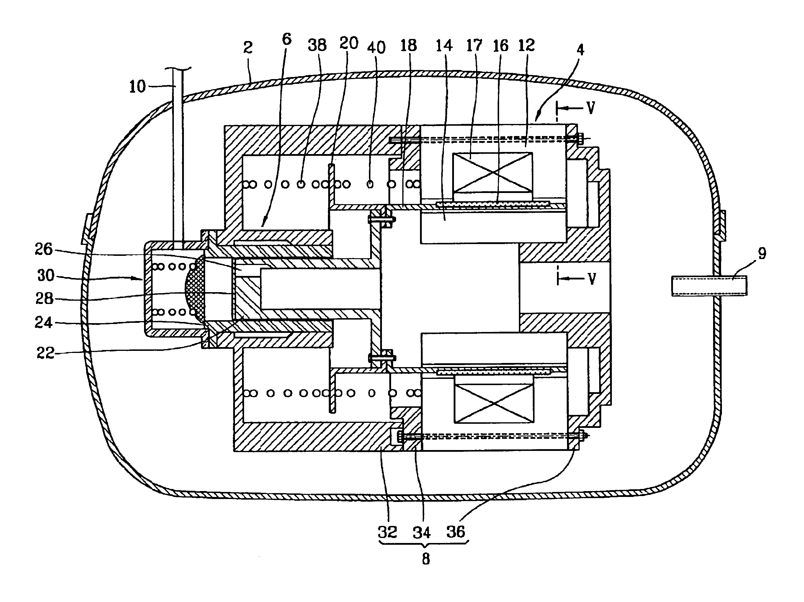
FIG. 4 is a sectional view illustrating a reciprocating compressor in accordance with the present invention.

The reciprocating compressor in accordance with the present invention includes a sealed casing 2; a motor unit 4 disposed in the casing 2 and generating a reciprocating motion force when power is applied; a compressing unit 6 receiving the reciprocating motion force generated at the motor unit 4 and performing a compression operation of the fluid; and a supporting unit 8 for supporting the motor unit 4 and the compressing unit 6.

A suction pipe 9 for sucking the fluid and a discharge pipe 10 for discharging the compressed fluid are respectively conne...


PUM


Abstract

In a reciprocating compressor including a first frame for supporting a cylinder of a compressing unit, a second frame for supporting a side of an outer stator of a motor unit and a third frame for supporting the other side of the outer stator and an inner stator of the motor unit, wherein the motor unit is arranged between the second and third frames, they are combined with each other, and the assembly is combined with the first frame. Accordingly, a reciprocating compressor is capable of reducing a fabrication cost by eliminating precise processing of construction parts and simplifying an assembly process by constructing a reciprocating motor as one assembly and combining it with a compressing unit.

Description

BACKGROUND OF THE INVENTION1. Field of the InventionThe present invention relates to a reciprocating compressor, and in particular to a reciprocating compressor which is capable of simplifying an assembly process and improving assembly strength by constructing a reciprocating motor as one assembly and combining it with a compressing unit.2. Description of the Prior ArtIn general, a compressor is classified into a rotary compressor, a reciprocating compressor and a scroll compressor, etc. according to fluid compressing methods.The reciprocating compressor compresses a fluid by a reciprocating motion of a piston by a reciprocating motor.FIG. 1 is a sectional view illustrating the conventional reciprocating compressor.The conventional reciprocating compressor includes a sealed casing 106 at which a suction pipe 102 and a discharge pipe 104 are connected; a motor unit 108 disposed in the casing 106 and generating a reciprocating motion force; a compressing unit 110 receiving the recipro...

Claims


Application Information

Patent Timeline
IPC IPC(8): F04B35/00F04B35/04F04B39/14F04B17/04H02K33/16
CPCF04B35/045Y10S417/902F04B17/04
Inventor PARK, KYEONG-BAEHEO, JONG-TAENOH, KI-WONLEE, JAE-MOCHOI, KI-CHUL
Owner INTELLECTUAL DISCOVERY CO LTD
Why Eureka
Try Eureka