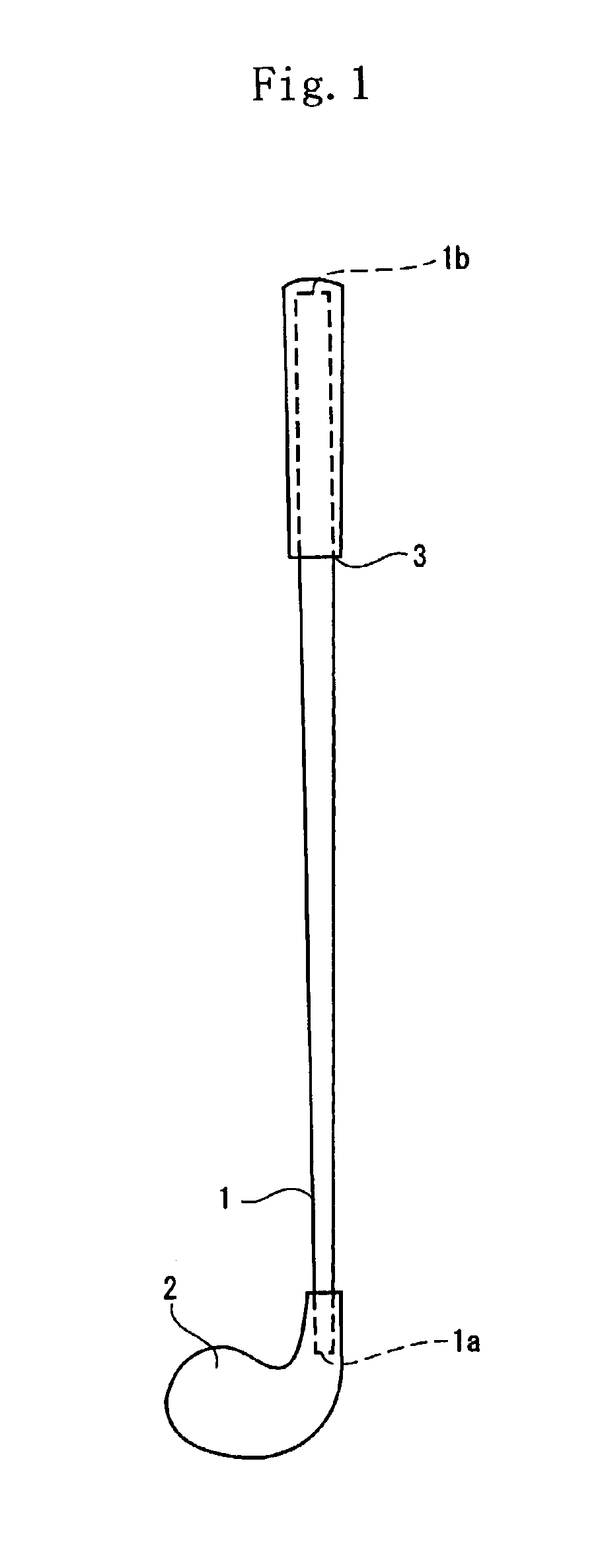
Golf club shaft

a golf club and shaft technology, applied in the field of golf club shafts, can solve the problems of increasing the weight of the shaft, preventing the intention of making the shaft lightweight, and the shaft is liable to be broken, so as to prolong the flight distance of the golf ball, reduce the torque, and improve the effect of strength

Inactive Publication Date: 2005-03-08
SUMITOMO RUBBER IND LTD
View PDF5 Cites 15 Cited by
  • Summary
  • Abstract
  • Description
  • Claims
  • Application Information

AI Technical Summary

Benefits of technology

The present invention has been made in view of the above-described problems. Therefore it is an object of the present invention to provide a golf club shaft lightweight to lengthen the flight distance of a golf ball hit with a golf club using the golf club shaft, having a low torque to stabilize the direction of the hit golf ball, and having such a high strength that it is not broken.

Problems solved by technology

However, to increase the amount of the prepregs of the angular layer leads to an increase of the weight of the shaft, which prevents the intention of making the shaft lightweight.
Because a material having a high tensile modulus of elasticity has a low strength, the shaft is liable to be broken.
Thus the pipe has a problem that it is difficult to make the shaft lightweight and a problem that the rigidity at the tip side of the shaft becomes too high.
Further if the outer diameter of the tip of the shaft is kept at the conventional diameter (φ8.5 mm-9.5 mm), a sufficient thickness cannot be obtained.
Thus a sufficient strength cannot be obtained and thus the shaft is liable to be broken.
Another problem is that in the case where a material having a tensile modulus of elasticity not less than 50 ton / mm2 is used to compose the reinforcing layer, the shaft is liable to be broken since the strength of the material is low.
Therefore a stress concentrates on the portion at which the tapering ratio of the mandrel changes greatly and the shaft is liable to be broken.

Method used


Image

  • Golf club shaft
  • Golf club shaft
  • Golf club shaft

Examples


second embodiment

A golf club shaft according to the present invention will be described below.

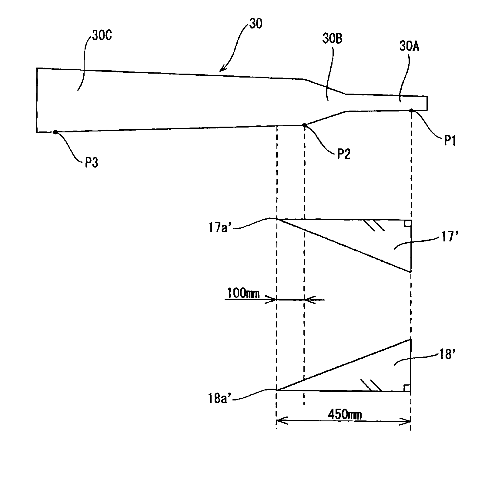
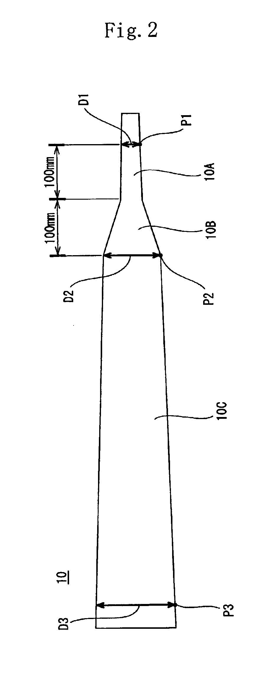
As shown in FIG. 4, a mandrel 20 to be used to produce the shaft according to the second embodiment of the present invention has a steeply tapered part 20A disposed at the tip side of the shaft 1 and having a steep tapering ratio of 16.5 / 1000 in the axial direction of the shaft 1; and a gently tapered part 20B continuous with the steeply tapered part 20A and having a gentle tapering ratio of 8 / 1000 in the axial direction thereof. The diameter of the mandrel 20 at a position P1 corresponding to the tip 1a of the shaft 1 is set to 4.4 mm. The diameter of the mandrel 20 at a position P2 disposed at the boundary between the steeply tapered part 20A and the gently tapered part 20B is set to 7.7 mm. The diameter of the mandrel 20 at a position P3 corresponding to the butt 1b of the shaft 1 is set to 14.2 mm.

The steeply tapered part 20A extends in a length of 200 mm from the position P1 corresponding to the tip 1a...

example 1

A golf club shaft was prepared by using a mandrel and prepregs similar to those of the first embodiment and a method similar to that of the first embodiment.

example 2

The butt-side end of each prepreg of the tip-side angular reinforcing layer was disposed at the butt side of the mandrel with respect to the boundary position between the steeply tapered part and the gently tapered part. The distance from the butt-side end of the prepreg to the boundary position, namely, the deviation of the butt-side end of the prepreg with respect to the boundary position-was set to 300 mm which is about 26.2% of the whole length of the shaft. The shaft was made by carrying out a method similar to that of the example 1 except that the number of turns of the tip-side prepreg was varied from that of the example 1.


PUM

PropertyMeasurementUnit
fibrous angleaaaaaaaaaa
angleaaaaaaaaaa

Abstract

A golf club shaft formed by winding prepregs of an angular layer and those of a straight layer around a mandrel (10) having a steeply tapered part (10B) formed at a tip side thereof and a gently tapered part (10C) formed, at a butt side thereof, continuously with the steeply tapered part (10B). Prepregs (17, 18) of the angular layer are disposed at the tip side of the mandrel (10). Butt-side ends (17a, 18a) of the prepregs (17, 18) of the angular reinforcing layer at the tip side of the mandrel (10) are disposed at the butt side of the mandrel (10) with respect to a boundary position (P2) disposed at a boundary between the steeply tapered part (10B) and the gently tapered part (10C). A distance from the butt-side ends (17a, 18a) of the prepregs (17, 18) of the angular reinforcing layer at the tip side of the mandrel (10) to the boundary position (P2) is not less than 5% nor more than 30% of a whole length of the shaft.

Description

This Nonprovisional application claims priority under 35 U.S.C. & 119(a) on patent application No. 2001-391356 filed in Japan on Dec. 25, 2001, which is herein incorporated by reference.BACKGROUND OF THE INVENTION1. Field of the InventionThe present invention relates to a golf club shaft and more particularly to a golf club shaft, made of a fiber reinforced resin, which is lightweight and improved in its strength and stability of the direction of a hit golf ball.2. Description of the Related ArtThe performance demanded for the golf club is to hit golf balls a long distance and make the direction thereof stabilized. As one means for complying with the demand of hitting the golf ball a long distance, research for making the shaft lightweight is performed. That is, by making the shaft lightweight, the golf club can be swung easily and the head speed thereof increases. Thus it is possible to make the flight distance of the golf ball longer.As one means for complying with the demand of s...

Claims


Application Information

Patent Timeline
Patent Type & Authority Patents(United States)
IPC IPC(8): A63B53/10A63B102/32B29C70/16B29C70/32B29L31/52
CPCA63B53/10A63B2209/02A63B59/0014A63B60/06A63B60/08A63B60/10
Inventor OYAMA, HITOSHI
Owner SUMITOMO RUBBER IND LTD
Why Eureka
Try Eureka