Direct methanol fuel cell stack

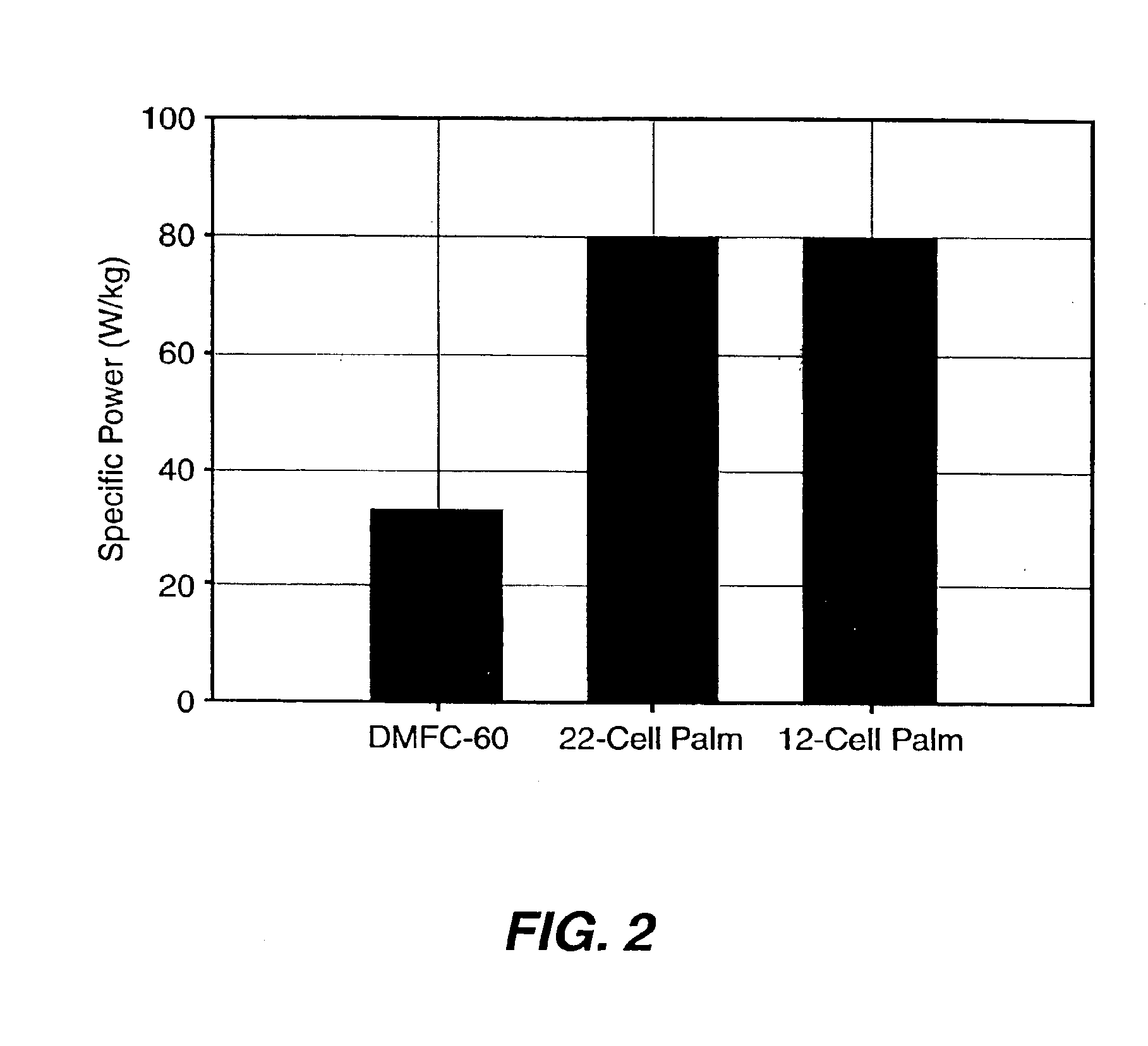
a fuel cell and methanol technology, applied in the field of fuel cell stacks, can solve the problems of 2 power loss, performance degradation, and specific power (w/kg) of the 22-cell palm power stack

Inactive Publication Date: 2005-03-08
LOS ALAMOS NATIONAL SECURITY
View PDF12 Cites 17 Cited by
  • Summary
  • Abstract
  • Description
  • Claims
  • Application Information

AI Technical Summary

Problems solved by technology

The performance by this design is detailed in FIG. 1, but specific power (W/kg), as detailed in FIG. 2, suffered due to the use of relatively heavy metal hardwar

Method used


Image

  • Direct methanol fuel cell stack
  • Direct methanol fuel cell stack
  • Direct methanol fuel cell stack

Examples


Embodiment Construction

, and 3c are pictorial illustrations of the present invention bipolar plate design.

[0016]FIG. 4 is an exploded view of the present invention bipolar plate unit cell.

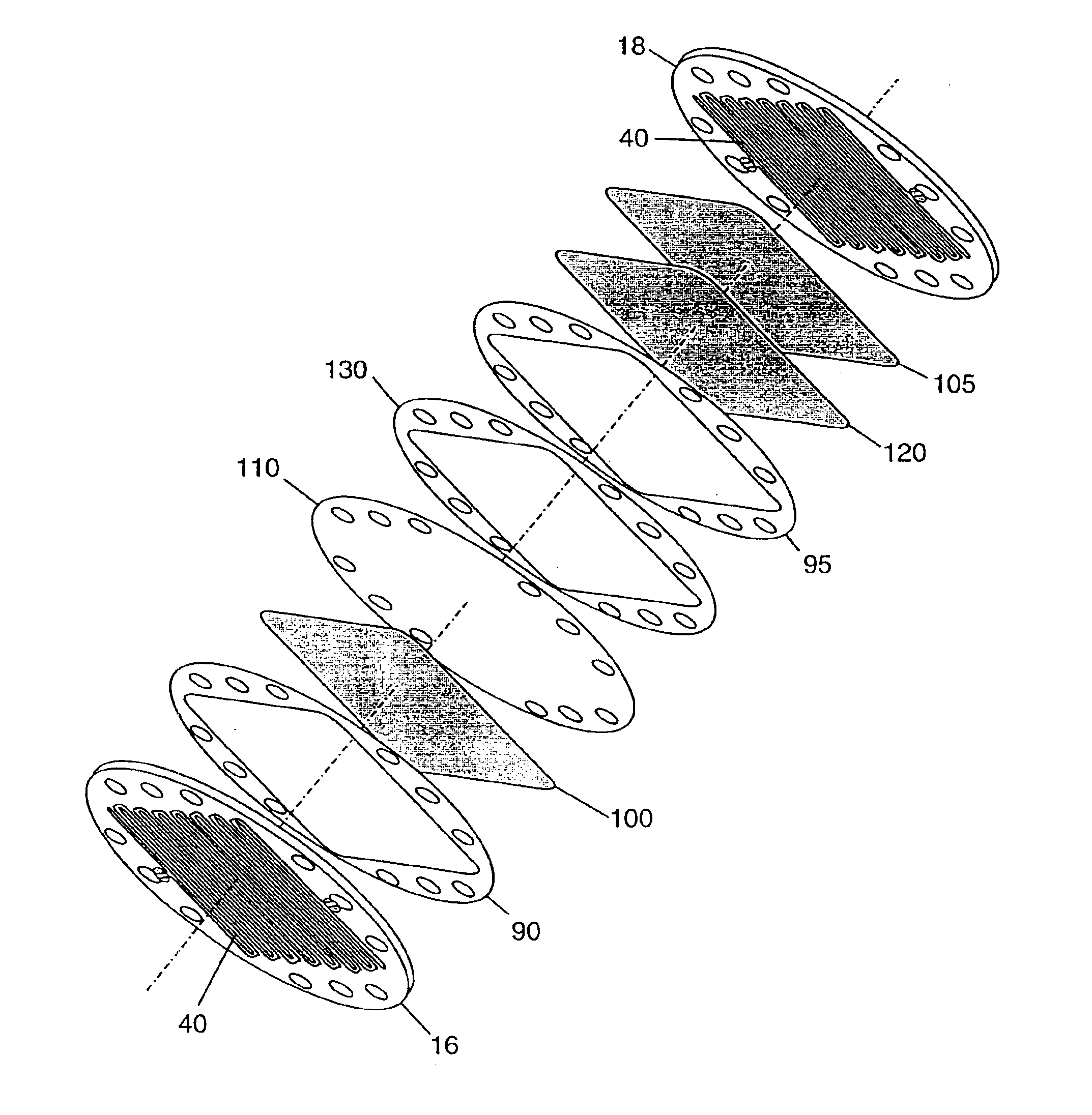
[0017]FIG. 5 is a pictorial illustration of one embodiment of the present invention fuel cell stack design.

[0018]FIG. 6 is a pictorial illustration of an end plate assembly design.

[0019]FIG. 7 is a pictorial illustration of the multifunctional endplate fuel cell stack design.

[0020]FIG. 8 is a pictorial illustration of a bipolar plate with voltage tap.

[0021]FIG. 9 is a pictorial illustration of a voltage measurement fixture.

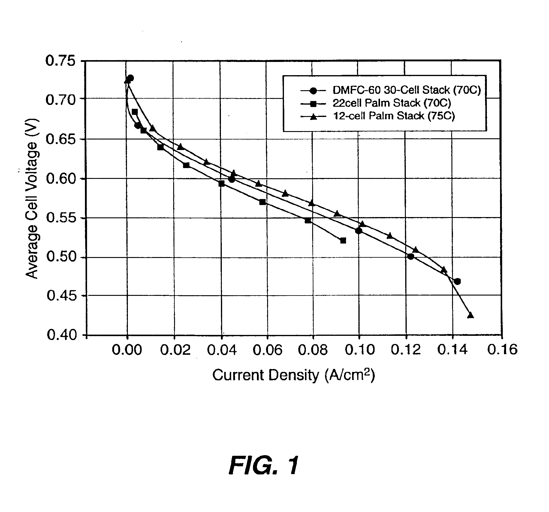
[0022]FIG. 10 graphically shows 6-cell stack anode polarization plots.

[0023]FIG. 11 graphically shows 6-cell stack DMFC performance plots.

DETAILED DESCRIPTION

[0024]Fuel cell technologies continue to provide new and innovative designs for fuel cells. The fuel cell and fuel cell stack embodiments according to the present invention take another step in reducing the fuel cell footprint, reducing the fuel c...


PUM


Abstract

A stack of direct methanol fuel cells exhibiting a circular footprint. A cathode and anode manifold, tie-bolt penetrations and tie-bolts are located within the circular footprint. Each fuel cell uses two graphite-based plates. One plate includes a cathode active area that is defined by serpentine channels connecting the inlet and outlet cathode manifold. The other plate includes an anode active area defined by serpentine channels connecting the inlet and outlet of the anode manifold, where the serpentine channels of the anode are orthogonal to the serpentine channels of the cathode. Located between the two plates is the fuel cell active region.

Description

RELATED APPLICATIONS[0002]This application claims the benefit of provisional application No. 60 / 460,162 filed on Apr. 3, 2003, titled “Efficient Fuel Cell Stack Design”.STATEMENT REGARDING FEDERAL RIGHTS[0003]This invention was made with government support under Contract No. W-7405-ENG-36 awarded by the U.S. Department of Energy. The government has certain rights in the invention.FIELD OF THE INVENTION[0004]The present invention relates generally to fuel cell stacks, and, more particularly, to cumulative fuel cell stack improvements yielding improved performance characteristics.BACKGROUND OF THE INVENTION[0005]There is significant and increasing interest in utilizing direct methanol fuel cells (DMFCs) for portable power applications. Currently, most attention is focused on DMFC sub-watt power systems that are relatively simple. However, more sophisticated systems, providing more than several watts of power, can provide higher power densities. Stack designs for such systems mirror co...

Claims


Application Information

Patent Timeline
IPC IPC(8): H01M2/00H01M2/02H01M2/08H01M2/14H01M8/02H01M8/24H01M8/00H01M8/10
CPCH01M8/0234H01M8/0258H01M8/2455H01M8/248H01M8/1011Y02E60/523Y02E60/50H01M8/241H01M8/2483H01M8/0263H01M8/0271
Inventor WILSON, MAHLON S.RAMSEY, JOHN C.
Owner LOS ALAMOS NATIONAL SECURITY
Why Eureka
Try Eureka