Rotational operation mechanism and music playback apparatus using the mechanism

a technology of rotational operation and music playback apparatus, which is applied in the direction of mechanical control devices, instruments, electrophonic musical instruments, etc., can solve the problems of difficult rotation, too large friction between the jog ring and the jog stay, and impossible smooth operation

Inactive Publication Date: 2005-03-08
PIONEER CORP
View PDF21 Cites 29 Cited by
  • Summary
  • Abstract
  • Description
  • Claims
  • Application Information

AI Technical Summary

Benefits of technology

According to still another aspect of the present invention, there is provided a music playback apparatus including: a base member; a ring member that is positioned on the base member and holds a plurality of rotatable balls; an annularly shaped rotation operation portion positioned on the ring member and operated by an operator; a playback unit for playing back music discs; and an operating switch member provided in a center portion of the annular member, wherein mutually facing surfaces of the base member and the rotation operation portion are provided with grooves that have substantially the same diameter as the ring member, the ring member is sandwiched between the base member and the rotation operation portion such that th...

Problems solved by technology

If the biasing force is too strong, the friction generated between the jog ring and the jog stay is too great and rotation becomes difficult.
If, on the other hand, the biasing force is too weak, then looseness occurs in the vertical direction and in the peripheral direction between the jog ring and the jog stay, and smooth operation becomes impossible.
As a result...

Method used


Image

  • Rotational operation mechanism and music playback apparatus using the mechanism
  • Rotational operation mechanism and music playback apparatus using the mechanism
  • Rotational operation mechanism and music playback apparatus using the mechanism

Examples


Embodiment Construction

Preferred embodiments of the present invention will now be described with reference to the attached drawings.

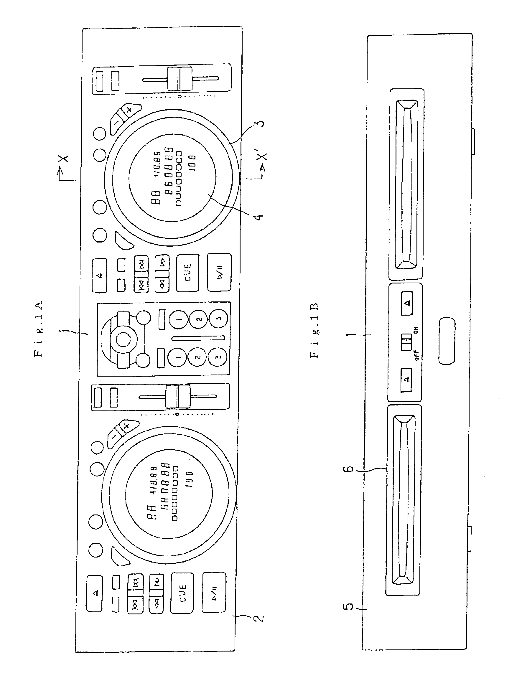
The exterior of the DJ apparatus according to the present invention is shown in FIGS. 1A and 1B. The DJ apparatus 1 is formed as a case substantially in the shape of a rectangular parallelepiped. FIG. 1A shows an operation panel 2 formed at the top face of the DJ apparatus 1, while FIG. 1B shows a front face panel 5 formed at a side face of the DJ apparatus 1.

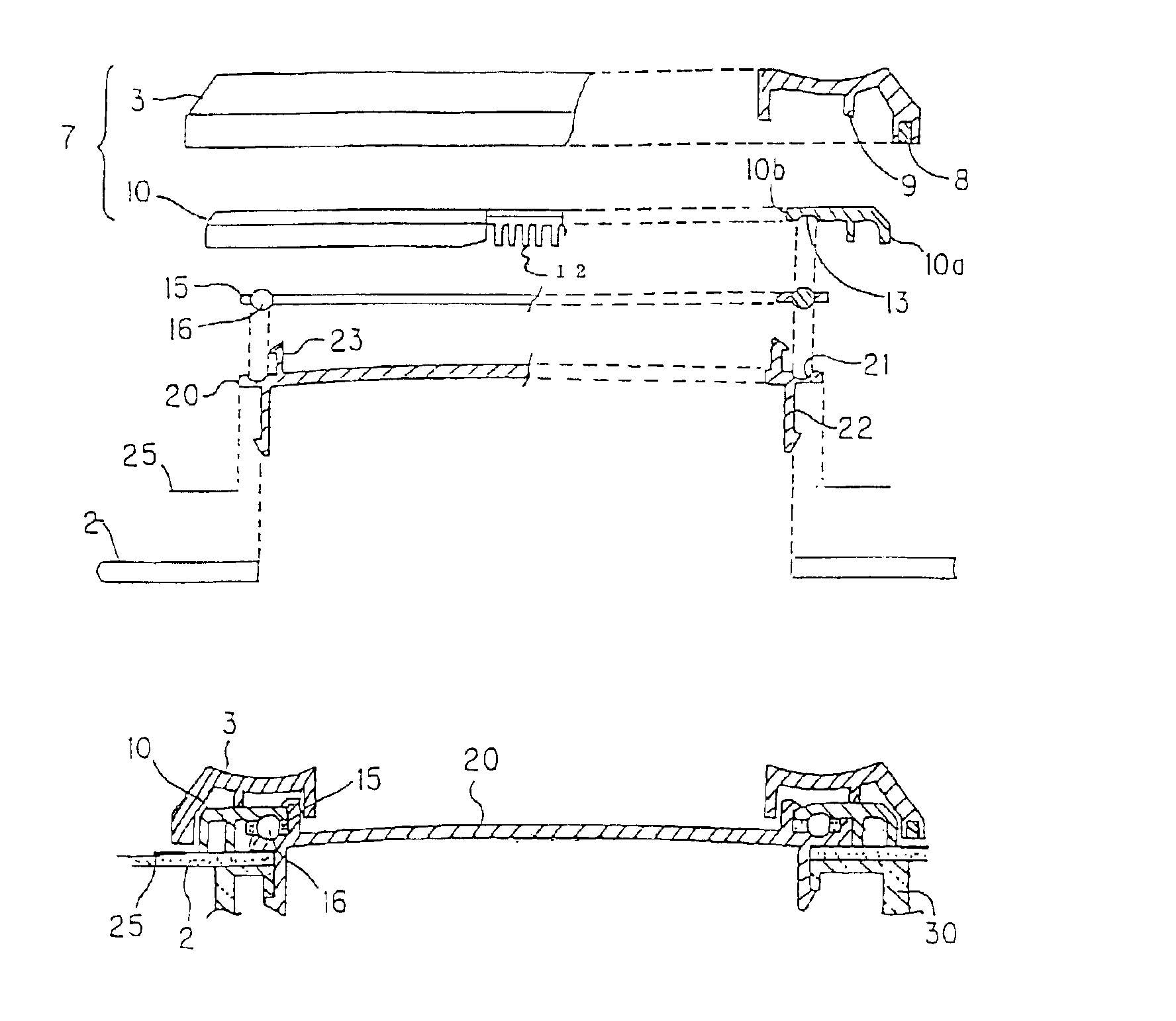
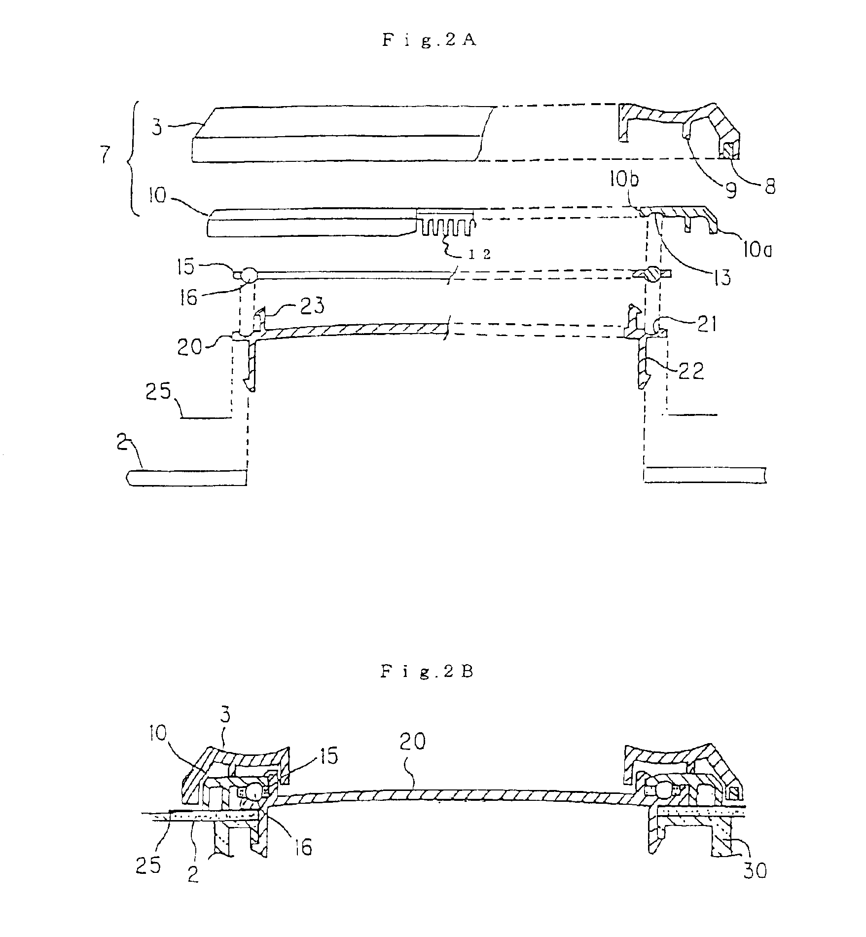
A pair of disc insertion openings 6 are provided at the front face panel 5, and music discs such as CDs are inserted into each disc insertion opening 6. The operation panel 2 is made of metal, and various switches and buttons for controlling playback of the music disc are provided on the operation panel 2. A pair of jog dials 3 are also provided at the left and right area of the operation panel 2. Playback of the music disc is controlled by a user rotating a jog dial 3 in a clockwise direction or a counterclockwise direc...


PUM


Abstract

A rotational operation mechanism for a DJ apparatus enables smooth rotation to be achieved using a simple configuration. A rotational operation mechanism has a base, a display window member fixed onto the base, a ring member positioned on the display window member and holding a plurality of rotatable balls, and a rotation operation portion positioned on the ring member and operated by an operator. Mutually facing surfaces of the display window member and the rotation operation portion are provided with grooves that have substantially the same diameter as the ring member. The ring member is sandwiched between the display window member and the rotation operation portion such that the plurality of balls are received in the groove of the display window member and the groove of the rotation operation portion, and the ring member is rotatable in a peripheral direction. One of the rotation operation portion and the base is provided with magnets and the other of the rotation operation portion, and the base is provided with metal portions at positions facing the magnets.

Description

BACKGROUND OF THE INVENTION1. Field of the InventionThe present invention relates to a rotational operation mechanism that performs a rotation movement in response to the operation of a user, and more particularly relates to a rotational operation mechanism that can be preferably employed as a portion of what is known as a disc jockey (DJ) apparatus.2. Description of the Related ArtIn what is known as a DJ apparatus, a disc such as a compact disc (CD) is inserted into the DJ apparatus via a disc insertion opening. A round operation portion known as a jog dial is provided on an operation panel. When the jog dial is manually rotated by a user, various playback instructions such as playback and search are input.In the rotational operation mechanism of a conventional jog dial, a sliding face known as a jog stay is fixed to the DJ apparatus body and a ring-shaped sliding member known as a jog ring is formed integrally with the jog dial and positioned so as to face the jog stay. When the ...

Claims


Application Information

Patent Timeline
IPC IPC(8): G11B19/20G11B27/00G10H1/00G11B19/00G05G1/00G05G1/10G05G1/015G11B33/02G11B33/12
CPCG10H1/0091G11B19/00G11B27/005G11B19/20G10H2210/241G11B2220/41G11B2220/2545
Inventor NOJIMA, YOSHITAKAMURATANI, KENJI
Owner PIONEER CORP
Why Eureka
Try Eureka