Servo signal recording device and servo signal verifying device using edge detection

a technology of servo signal and recording device, which is applied in the direction of maintaining head carrier alignment, recording/reproducing head alignment, and track following on tape, etc., can solve the problems of reducing productivity and yield, affecting the accuracy of recording/recording track, and incurring a great burden in cost and labor

Inactive Publication Date: 2005-03-08
FUJIFILM CORP +1
View PDF11 Cites 43 Cited by
  • Summary
  • Abstract
  • Description
  • Claims
  • Application Information

AI Technical Summary

Benefits of technology

Preferably, the adjusting means allows the recording means to move along the crosswise dir

Problems solved by technology

In response to this demand, there is a tendency for the width of the information recording track to become narrower, whereby it becomes difficult for the recording/reproducing head to track the recording track accurately.
However, factors such as the degree of precision of the transporting system and fluctuations in the shape of the tape (i.e., width, thickness) cause the transported magnetic tape to move (i.e., displacement attendant on transporting occurs) in the crosswise direction at the servo signal recording position, and this causes the servo signal recording position to fluctuate along the crosswise direction.
However, when the positional regulation for the transporting system is strengthened, a strong force is borne on the edge (side portion) of the magnetic tape, and there was a problem in that deformation, breakage and the like occur in the magnetic tape, which disadvantageously result

Method used


Image

  • Servo signal recording device and servo signal verifying device using edge detection
  • Servo signal recording device and servo signal verifying device using edge detection

Examples


Embodiment Construction

Hereinafter, detailed explanation is made of a servo signal recording device according to a first aspect of the present invention, and a servo signal verifying device according to a second aspect of the present invention, based on a preferred embodiment shown in the attached drawings.

Note that, in the following explanations, unless otherwise indicated, the term “position” refers to a position along a crosswise direction of a tape T.

First, explanation will be made of the servo signal recording device according to the first aspect of the present invention.

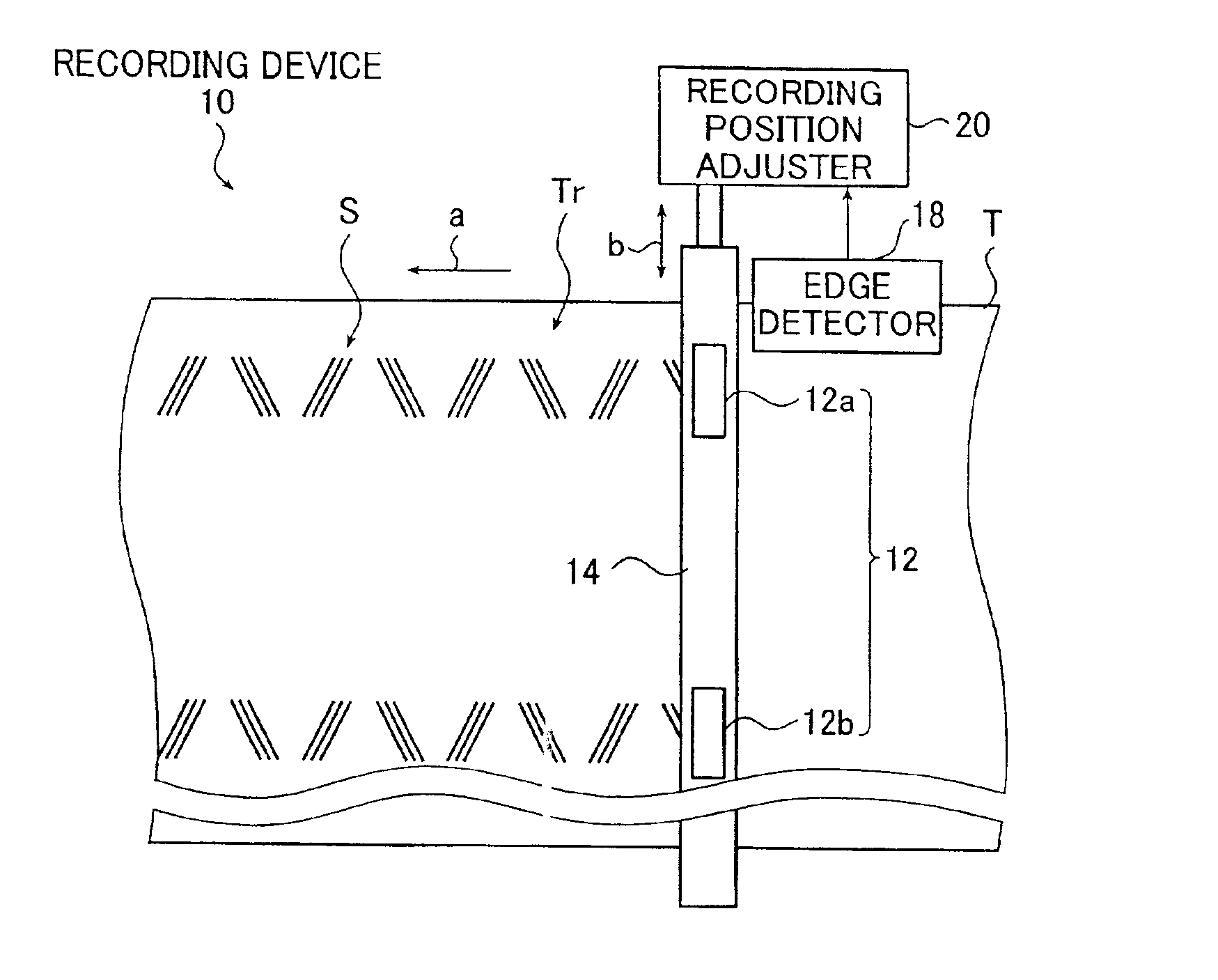
FIG. 1 shows a conceptual diagram of an embodiment of the servo signal recording device in accordance with the first aspect of the present invention.

A servo signal recording device (hereinafter, referred to as recording device) 10 shown in FIG. 1 is a device which transports a long magnetic tape T (hereinafter, referred to as tape T) while recording a servo signal S by means of a servo signal recording head 12, comprising as its basi...


PUM


Abstract

The servo signal recording device records a servo signal onto a magnetic tape. The device includes a transporting unit for transporting the magnetic tape along its lengthwise direction, a recording unit for recording the servo signal onto the transported magnetic tape, a detecting unit for detecting an edge of the magnetic tape at a time when the servo signal is recorded and an adjusting unit for adjusting a recording position of the servo signal along a crosswise direction of the magnetic tape in accordance with a detection result of the edge of the magnetic tape by the detecting unit. The servo signal verifying device verifies a servo signal recorded onto a magnetic tape. The device includes a reproducing unit for reproducing the servo signal, a detecting unit for detecting an edge of the magnetic tape at a time when the reproducing unit reproduces the servo signal and a calculating unit for calculating a verification result of the servo signal recorded onto the magnetic tape using a reproduction result of the servo signal and a detection result of the edge.

Description

BACKGROUND OF THE INVENTION1. Field of the InventionThe present invention belongs to a technical field of recording a servo signal onto a magnetic tape and verifying the servo signal recorded on the magnetic tape. More specifically, the invention relates to a servo signal recording device capable of recording the servo signal at a given position on the magnetic tape with a high degree of precision, and a servo signal verifying device capable of detecting only an error in the position at which the servo signal is recorded, to perform the verification of the servo signal with a high degree of precision.2. Description of the Related ArtIn a field where a magnetic tape is used to record information, in order to perform appropriate record / reproduction of the information, a magnetic head which records / reproduces the information (hereinafter, also referred to as recording / reproducing head) must track a recording track on the magnetic tape accurately.On the other hand, in recent years, ther...

Claims


Application Information

Patent Timeline
IPC IPC(8): G11B5/592
CPCG11B5/5928
Inventor NAKAO, TORUTATEISHI, SEIJI
Owner FUJIFILM CORP
Why Eureka
Try Eureka