Method and system for queuing traffic in a wireless communications network

a wireless communication and traffic technology, applied in the field of wireless communication, can solve the problems of limiting effective application throughput, overall network efficiency, and reducing so as to reduce congestion in the wireless network, reduce congestion, and reduce congestion. the effect of delivering ip packets into a region

Inactive Publication Date: 2005-03-08
CISCO TECH INC
View PDF41 Cites 340 Cited by
  • Summary
  • Abstract
  • Description
  • Claims
  • Application Information

AI Technical Summary

Benefits of technology

Another technical advantage of the present invention includes providing an improved method and system for organizing flows in a wireless network. In particular, flows are aggregated into groups based on location, radio frequency (RF) interference and/or other characteristics of the flows. This enables individual treatments to be applied to each of the groups and collections of network users to be given the same flow treatment.
Yet another technical advantage of the present invention includes providing an improved method and system for delivering packets in a cell site, sector or other region of a wireless network. In particular, flow locations and RF interference characteristics are utilized to allocate queuing and forwarding resources to flows and to provide congestion management for the flows in the network. Thus, the impact of delivering IP packets into a region is taken into account and conflicts between users are minimized.
Yet another technical advantage of the present invention includes providing a method and system for dynamically organizing flows in a wireless network. In particular, flows are grouped and regrouped into virtual location-specific, RF-specific or other flow aggregates based on changing flow locations, system and flow RF characteristics as well as interference implications. Thus, flow treatments are developed and modified based on location, system and RF character and the interference impact of the flow.
Yet another technical advantage of the present invention

Problems solved by technology

This limits effective application throughput, consistency across t

Method used


Image

  • Method and system for queuing traffic in a wireless communications network
  • Method and system for queuing traffic in a wireless communications network
  • Method and system for queuing traffic in a wireless communications network

Examples


Embodiment Construction

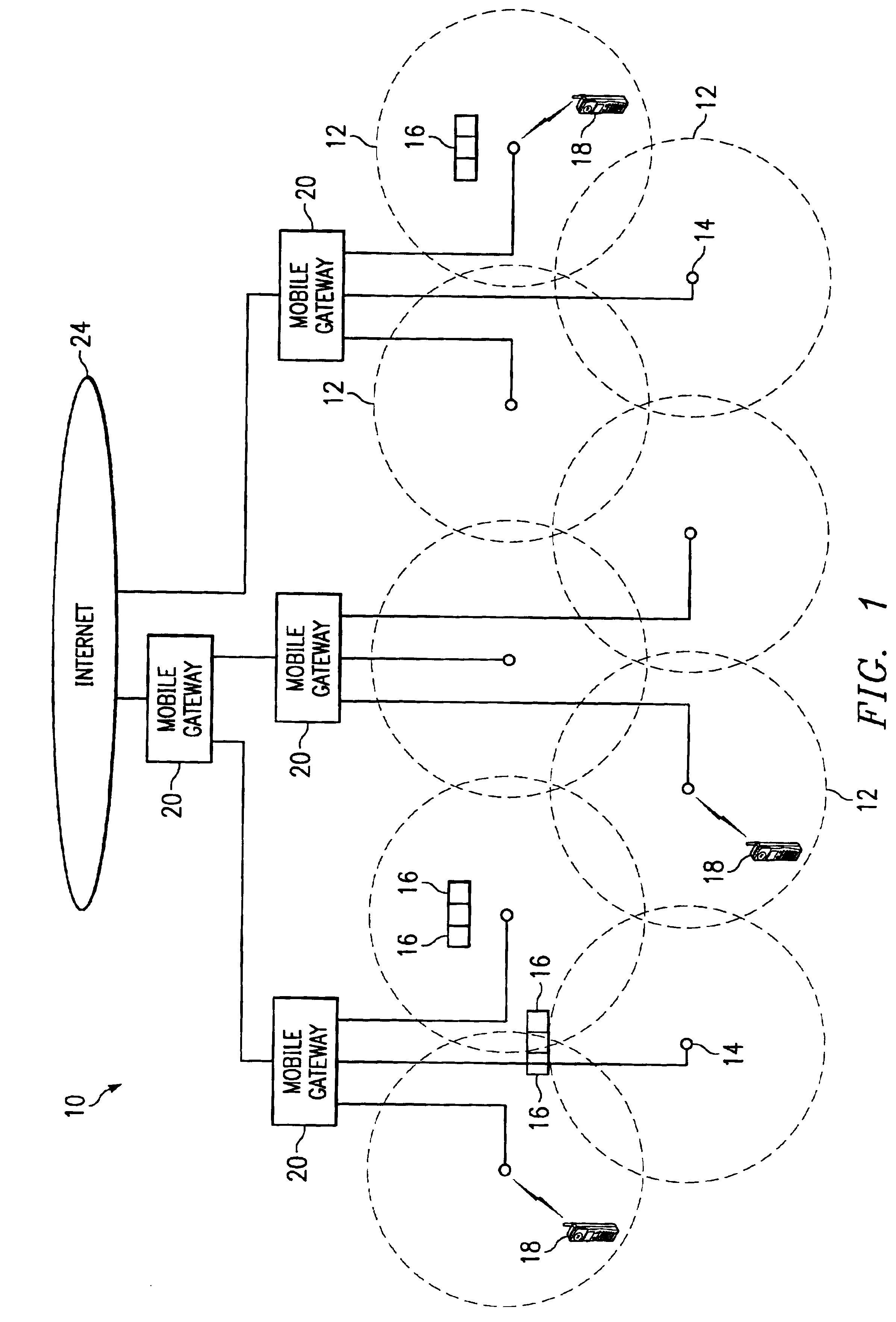
FIG. 1 illustrates a wireless network 10 in accordance with one embodiment of the present invention. In this embodiment, the wireless network 10 is a cellular network in which terrestrial wireless transmission originates in geographically delimited cells. It will be understood that the present invention may be used in connection with satellite and other suitable wireless and other dynamic bandwidth networks in which bandwidth over a link varies over time.

Referring to FIG. 1, the wireless network 10 covers a contiguous area that is broken down into a series of overlapping cells 12. Each cell 12 has a base station, or server, 14 and may be subdivided into a plurality of geo-location areas 16. The geo-location areas 16 are each a defined area in which bandwidth may be allocated to mobile devices. The geo-location areas 16 may have a resolution greater than, less than, or equal to cell size. In a particular embodiment, the geo-location areas 16 are substantially square in shape to form ...


PUM


Abstract

A method and system for queuing traffic in a wireless network includes receiving a stream of packets for transmission in the wireless network. Each packet includes a flow identifier and is assigned to one of the plurality of virtual groups based on the flow identifier. The virtual groups include discrete transmission resources. Each packet is queued in an assigned virtual group for transmission in the wireless network.

Description

TECHNICAL FIELD OF THE INVENTIONThe present invention relates generally to the field of wireless communications, and more particularly to a method and system for queuing traffic in a wireless communications network.BACKGROUND OF THE INVENTIONWireline and wireless Internet protocol (IP) networks have traditionally supported a best effort delivery of all traffic. To support enhanced services, multiple types, or classes, of services have been established and assigned certain quality of service (QoS) parameters that manage queues for each service type. The QoS parameters include delay, jitter, error rates, and throughput. The QoS parameters can be provisioned on a per IP connection or per flow basis through mechanisms such as resource reservation protocol (RSVP) or can be provisioned on aggregate flow which are classified into service classes. Internet service providers (ISPs) can utilize the service classes, their associated QoS behavior and QoS provisioning to provide tiered service o...

Claims


Application Information

Patent Timeline
IPC IPC(8): H04Q7/38H04Q7/36H04L12/56H04W16/24H04W28/14H04W28/24H04W64/00H04W80/00
CPCH04L47/12H04L47/2408H04L49/90H04W28/14H04W80/00H04W28/24H04W64/00H04W16/24
Inventor PATEL, PULIN R.PATEL, ACHAL R.CHOKSI, OJAS T.ALI, MOHAMMAD R.
Owner CISCO TECH INC
Why Eureka
Try Eureka