Method and system for digital signal transmission

a digital signal and transmission method technology, applied in transmission, amplitude-modulated carrier systems, modulated carrier systems, etc., can solve problems such as fading of received signals, affecting the design of mobile terminals, and increasing equipment design requirements of wireless systems

Inactive Publication Date: 2005-03-08
UNWIRED BROADBAND INC
View PDF19 Cites 198 Cited by
  • Summary
  • Abstract
  • Description
  • Claims
  • Application Information

AI Technical Summary

Benefits of technology

An equal distribution of transmission power between different antennas is also achieved by means of the solution of the invention. The solution of the invention preferably also provides coding in which the ratio of the maximum power to the average power or the ratio of the average power to the minimum power can be minimized.

Problems solved by technology

As wireless communication systems evolve, wireless system design has become increasingly demanding in relation to equipment and performance requirements.
Concurrent with the system service performance requirements will be equipment design constraints, which will strongly impact the design of mobile terminals.
Time-varying multi-path fading is an effect in wireless systems whereby a transmitted signal propagates along multiple paths to a receiver causing fading of the received signal due to the constructive and destructive summing of the signals at the receiver.
Each of these techniques, however, has drawbacks in regard to use for third and fourth generation wireless systems.
Time interleaving may introduce unnecessary delay, spread spectrum techniques may require large bandwidth allocation to overcome a large coherence bandwidth, and power control techniques may require higher transmitter power than is desirable for sophisticated receiver-to-transmitter feedback techniques that increase mobile station complexity.
All of these drawbacks have negative impact on achieving the desired characteristics for third and fourth generation mobile terminals.
A drawback of diversity reception is that the physical separation required between antennas may make diversity reception impractical for use on the forward link in the new wireless systems where small mobile station size is desired.
Rate in the context of space-time block code may be understood as inefficiency in use of the antenna resources, leading to dilution of maximal bit-rates as compared to the inherent capacity of the underlying wireless system specifications.
This inefficient use of antenna resources may give rise to fluctuating of transmit powers.
Such fluctuation of transmit powers is referred to as the power-unbalance problem.
However, extension of the Alamouti method to more than two antennas is not straightforward.
This method has a disadvantage in a loss in transmission rate and the fact that the multi-level nature of the ST coded symbols increases the peak-to-average ratio requirement of the transmitted signal and imposes stringent requirements on the linear power amplifier design.
These codes are not delay-optimal.
A drawback of the above solutions is that only the requirements 1 and 2 can be fulfilled.
This causes problems in the planning of output amplifiers.
Furthermore, the code rate is not optimal.
For 3 and 4 antennas, this maximal rate is ¾. Because of the inefficiency of codes with rates less than one (R<1) transmit power of a given antenna fluctuates in time; thus, presenting a power-unbalanced problem.

Method used


Image

  • Method and system for digital signal transmission
  • Method and system for digital signal transmission
  • Method and system for digital signal transmission

Examples


Embodiment Construction

The invention may be used in radio systems which allow the transmission of at least a part of a signal by using at least three or more transmit antennas or three or more beams that are accomplished by any number of transmit antennas. A transmission channel may be formed by using a time division, frequency division or code division multiple access method. Also systems that employ combinations of different multiple access methods are in accordance with the invention. The examples describe the use of the invention in a universal mobile communication system utilizing a broadband code division multiple access method implemented with a direct sequential technique, yet without restricting the invention thereto.

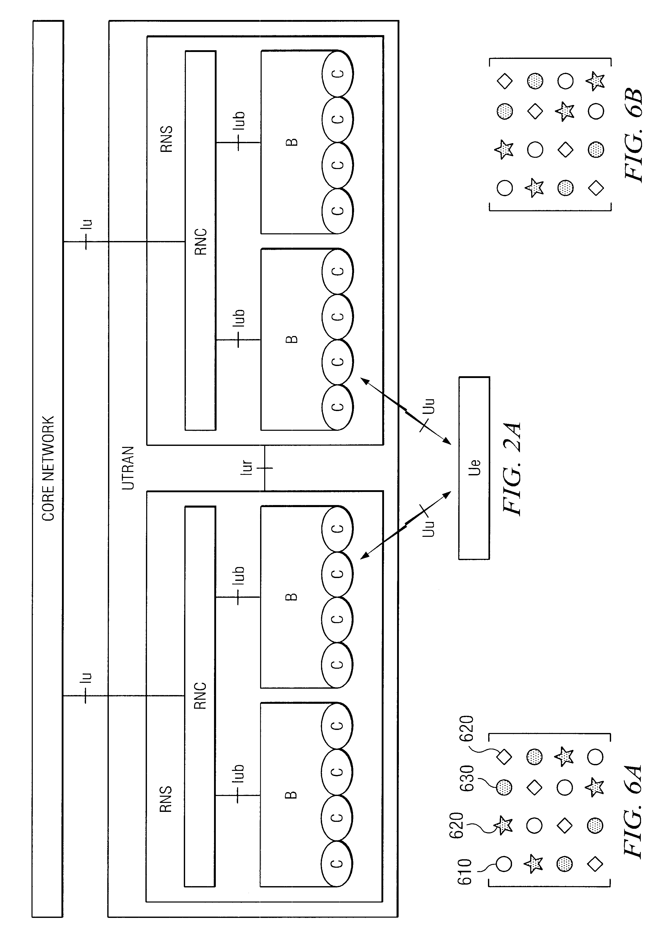
Referring to FIG. 2A, a structure of a mobile communication system is described by way of example. The main parts of the mobile communication system are core network CN, UMTS terrestrial radio access network UTRAN and user equipment UE. The interface between the CN and the UTRAN is c...


PUM


Abstract

The invention relates to a method and an arrangement for transmitting a digital signal consisting of symbols, which arrangement comprises a coder (308) for coding complex symbols to channel symbols in blocks having the length of a given K, means (312) for transmitting the channel symbols via several different channels and two or more antennas (314 to 318). The coder (308) is arranged to code the symbols using a code matrix, which can be expressed as a sum of 2K elements, in which each element is a product of a symbol or symbol complex conjugate to be transmitted and a N×N representation matrix of a complexified anti-commutator algebra, extended by a unit element, and in which each matrix is used at most once in the formation of the code matrix. A code matrix is also provided which is formed by matrices of a portion of the symbols placed on the diagonal of the code matrix and by matrices of a second portion of symbols along the anti-diagonal of the code matrix.

Description

FIELD OF THE INVENTIONThis invention relates generally to methods and systems for achieving transmit diversity in a telecommunication system. More particularly, the present invention relates to an apparatus and associated method for using a space-time block code to reduce bit error rates of a wireless communication in a spread spectrum receiver.Mathematical FoundationsThe review of mathematical tools, nomenclature, and notations follows which is intended to be used for an understanding of the present invention. Multiple notations may be used in same parts of the application to better describe the invention. Other mathematical techniques, nomenclature, and notations may be used to describe the present invention without departing from the spirit and scope thereof.A vector may be represented in Dirac notation proposed by P.A.M. Dirac:Bra a| which may be represented by a row matrix or αi=[α1,α2,α3]Ket |b which may be represented by a column matrix βi=[β1β2β3];andC is defined as =∑i⁢l❘i〉...

Claims


Application Information

Patent Timeline
Patent Type & Authority Patents(United States)
IPC IPC(8): H04L27/02H04L27/04H04L1/06
CPCH04B7/0669H04L1/0618H04L1/06
Inventor BOARIU, ADRIANHOTTINEN, ARITIRKKONEN, OLAV
Owner UNWIRED BROADBAND INC
Why Eureka
Try Eureka