Code-switched optical networks

a technology of optical networks and code switches, applied in the field of optical communication systems and methods, can solve the problems of high cost of providing multiple lasers, and high cost of to-electronic-to-optical conversion at each network nod

Inactive Publication Date: 2005-03-08
MICRON TECH INC
View PDF9 Cites 51 Cited by
  • Summary
  • Abstract
  • Description
  • Claims
  • Application Information

AI Technical Summary

Problems solved by technology

Such optical-to-electronic-to-optical conversion at each network node requires expensive active equipment that generally must operate at the full network bandwidth.
Unfortunately, telecommunication-grade tunable lasers are not readily available, and providing multiple lasers is expensive.

Method used


Image

  • Code-switched optical networks
  • Code-switched optical networks
  • Code-switched optical networks

Examples


Embodiment Construction

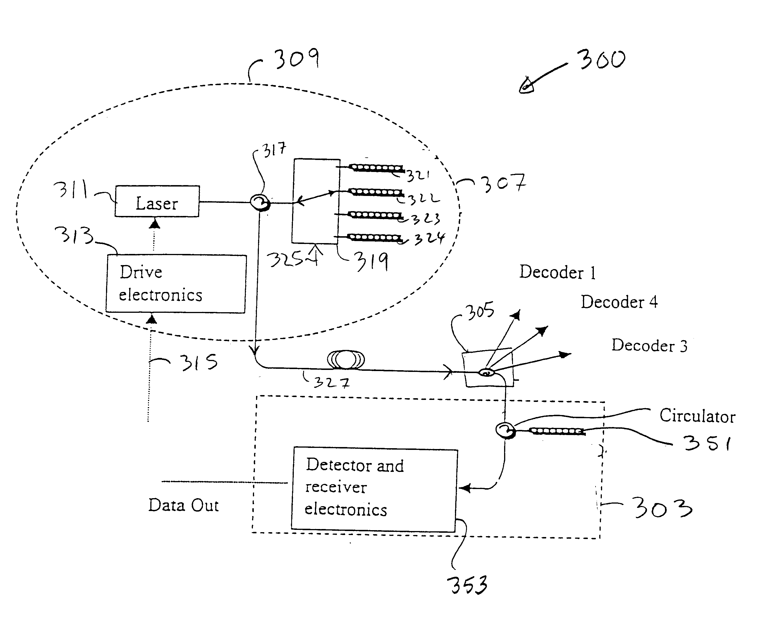
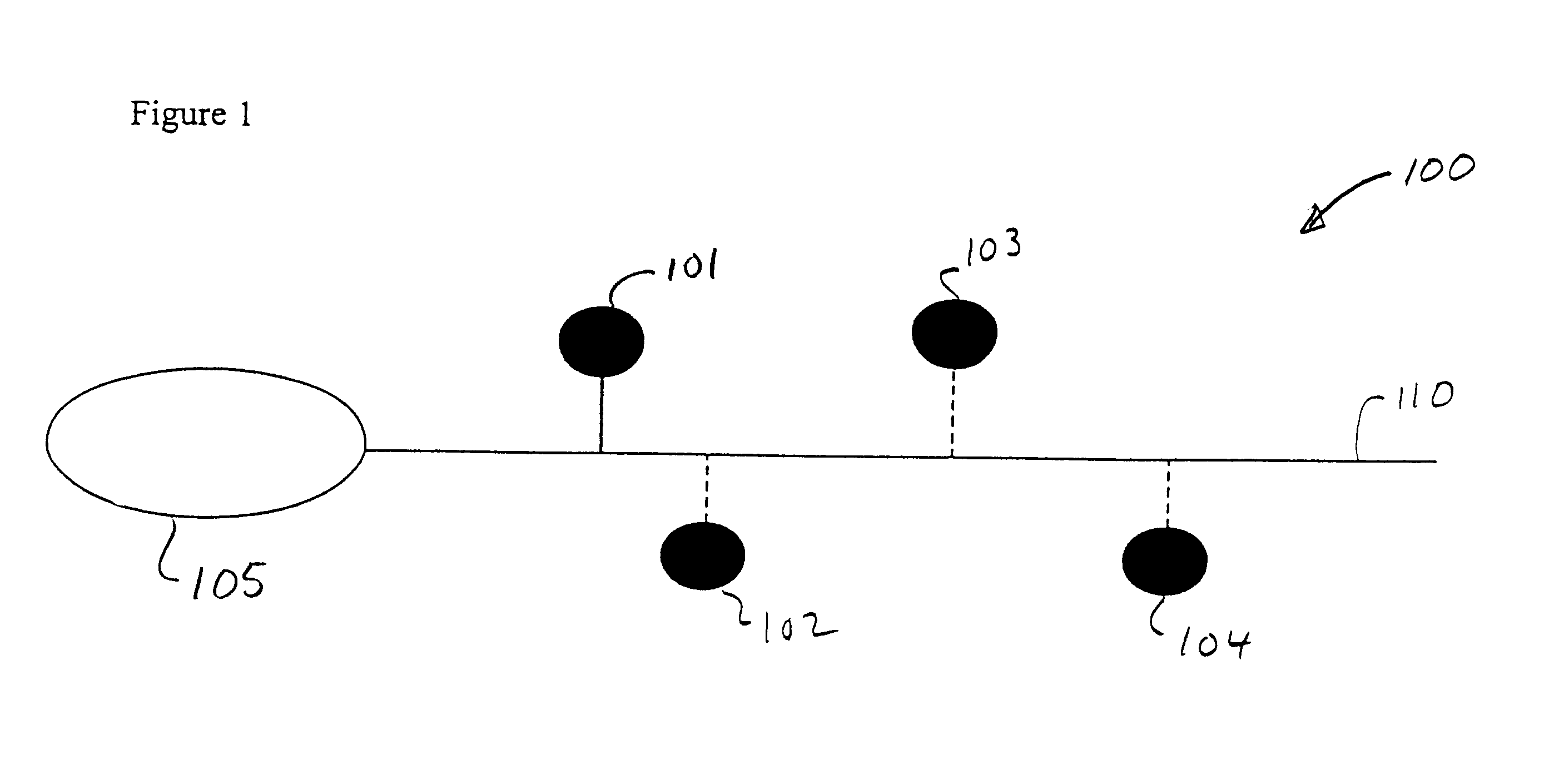
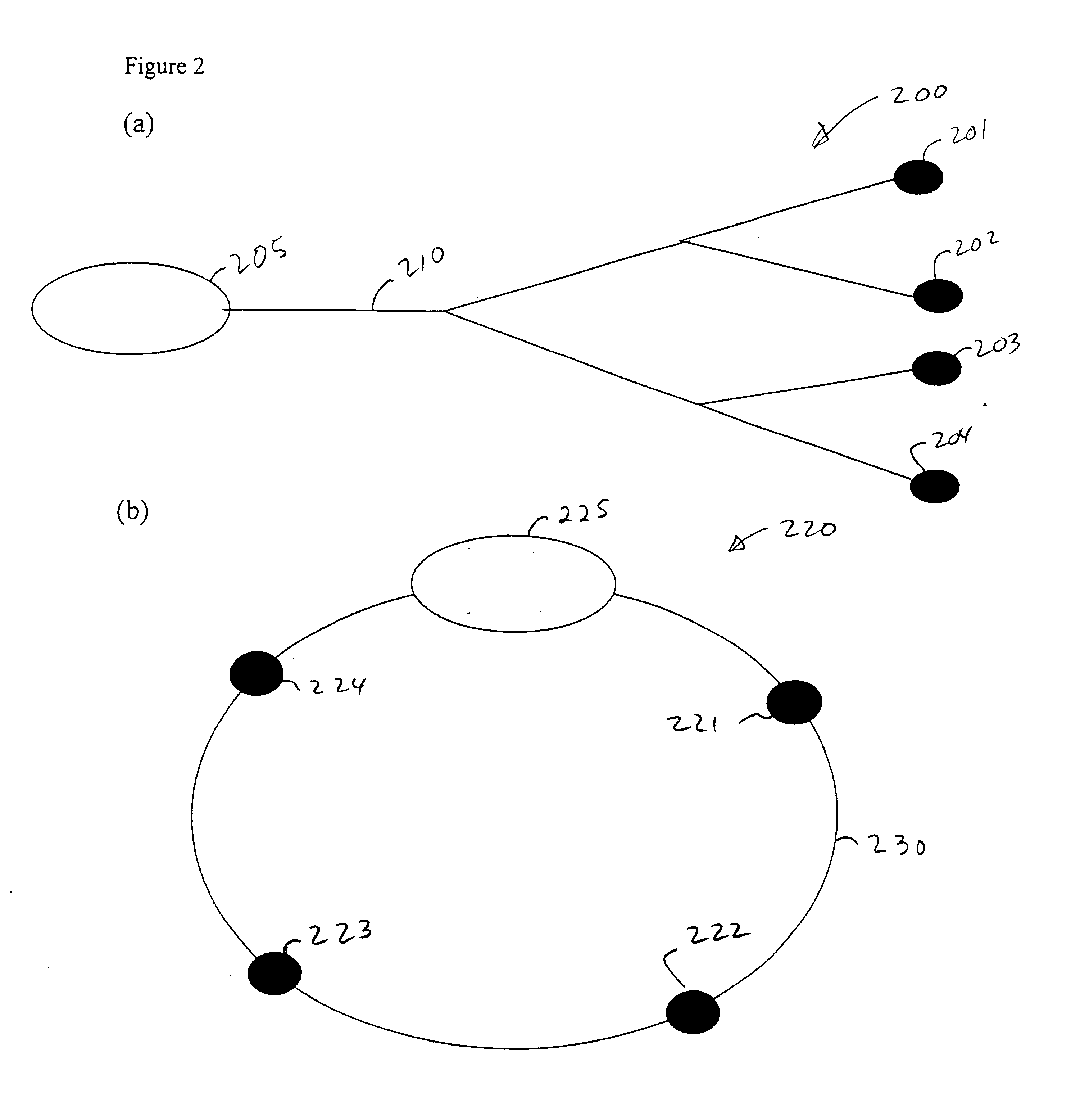
Communication systems, networks, and methods are disclosed that do not require active switching elements outside of a master node, but rather use optical coding to route or switch optical data streams to one or more of several destinations. Optical codes are applied to the optical data streams to determine the destination of the data, i.e., destinations are selected based on optical codes. Such systems are referred to herein as “code-switched.” A representative communication system includes a master node that transmits an optical signal to a remote node selected from a set of remote nodes. The master node directs the optical signal to the selected remote node by encoding the signal with a remote-node-specific optical code (“channel code”). Channel codes can be amplitude codes, frequency codes, or phase codes, or combinations thereof. Channel codes can be binary codes or can have three or more associated code values. For example, a channel code can be defined as a series of code elem...


PUM


Abstract

Communication systems and methods are disclosed that route, detect, and decode encoded optical signals at network nodes based on channel codes assigned to the network nodes. In an example communication system, a network hub includes a channel selector that encodes an optical signal with a channel code assigned to one or more network nodes. The channel selector is configured to encode based on a channel selection signal provided to the channel selector and can include one or more fiber Bragg coders. Code-switched communication systems can include one or more nodes configured in ring, tree, or bus architectures.

Description

TECHNICAL FIELDThe invention pertains to optical communication systems and methods.BACKGROUNDCommunication systems that include master node / remote node communication include the Synchronous Optical Network (SONET) and Asynchronous Transfer Mode (ATM) networks in which optical data signals are converted into electronic signals at each node of the network. The electronic signals are then decoded in order to make routing decisions before data is retransmitted optically down a selected path. Such optical-to-electronic-to-optical conversion at each network node requires expensive active equipment that generally must operate at the full network bandwidth.One all-optical routing method that reduces the number of optical-electronic conversions is wavelength division multiplexing (WDM) in which different nodes of a network receive different optical signals having different center wavelengths. A communication hub sends data to a selected destination by selecting a suitable wavelength, either ...

Claims


Application Information

Patent Timeline
Patent Type & Authority Patents(United States)
IPC IPC(8): H04J14/00
CPCH04J14/005
Inventor JOHNSON, ALAN E.MUNROE, MICHAEL J.GRUNNET-JEPSEN, ANDERSMANILOFF, ERIC S.SWEETSER, JOHN N.
Owner MICRON TECH INC
Why Eureka
Try Eureka