
Electronics assembly engineering system employing naming and manipulation functions for user defined data structures in a data system using transaction service

a technology of data structure and data system, applied in the field of electronic assembly engineering systems, can solve the problems of complex and sophisticated subsystems, insufficient naming and manipulation functions of traditional file-based systems, and inability of programmers to work with the system to manipulate data structures in the same manner as they did in traditional file-based systems

Inactive Publication Date: 2005-03-08
SIEMENS ELECTRONICS ASSEMBLY SYST LLC +1
View PDF20 Cites 16 Cited by
  • Summary
  • Abstract
  • Description
  • Claims
  • Application Information

AI Technical Summary

Problems solved by technology

Electronics assembly engineering systems for industrial applications require complex and sophisticated subsystems to control performance of each system and to account for changes in the application parameters and the industrial environment.
However, in this instance, where the electronics assembly engineering system and computer subsystem employ transaction service and the data structures have referential integrity, programmers working with the system can no longer expect to manipulate the data structures in the same manner as they did in traditional file-based systems.
The naming and manipulation functions of the traditional file-based systems are not adequate for operating in object-oriented systems using transaction service where data structures have referential integrity.
The result is that the user does not see the object browser.Objects that are opened in an editor are immediately updated when changes are made—there is no copy of the object in memory.Objects can have many names or aliases—this leads to a certain amount of ambiguity in that an ordinary user may have trouble visualizing where an object exists.

Method used


Image

  • Electronics assembly engineering system employing naming and manipulation functions for user defined data structures in a data system using transaction service
  • Electronics assembly engineering system employing naming and manipulation functions for user defined data structures in a data system using transaction service
  • Electronics assembly engineering system employing naming and manipulation functions for user defined data structures in a data system using transaction service

Examples


Embodiment Construction

and functions.

BRIEF DESCRIPTION OF THE DRAWINGS

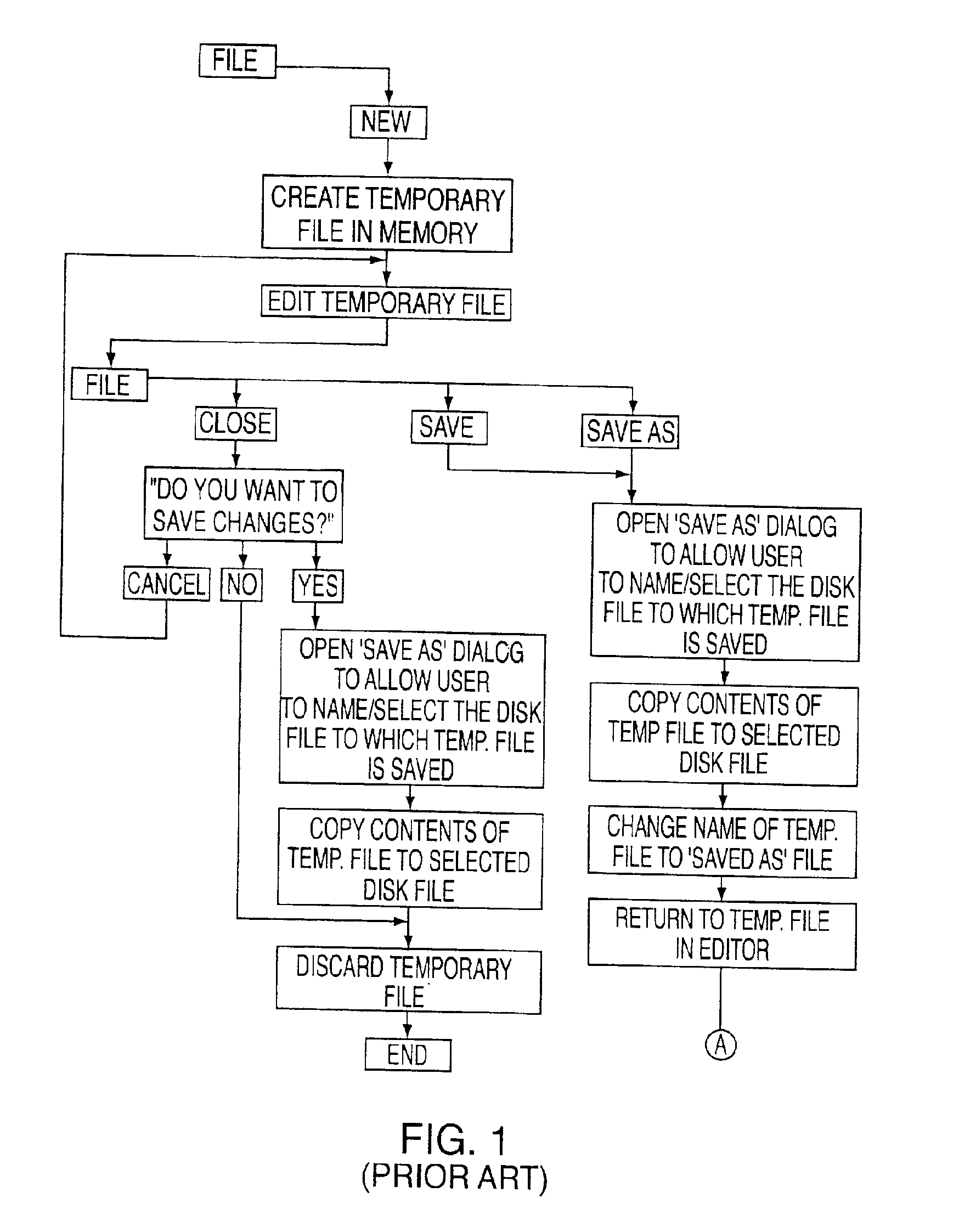
[0033]FIG. 1 shows a flowchart of the basic functionality and menu functions of a prior art file-based editor in the mode where a new file is being created.

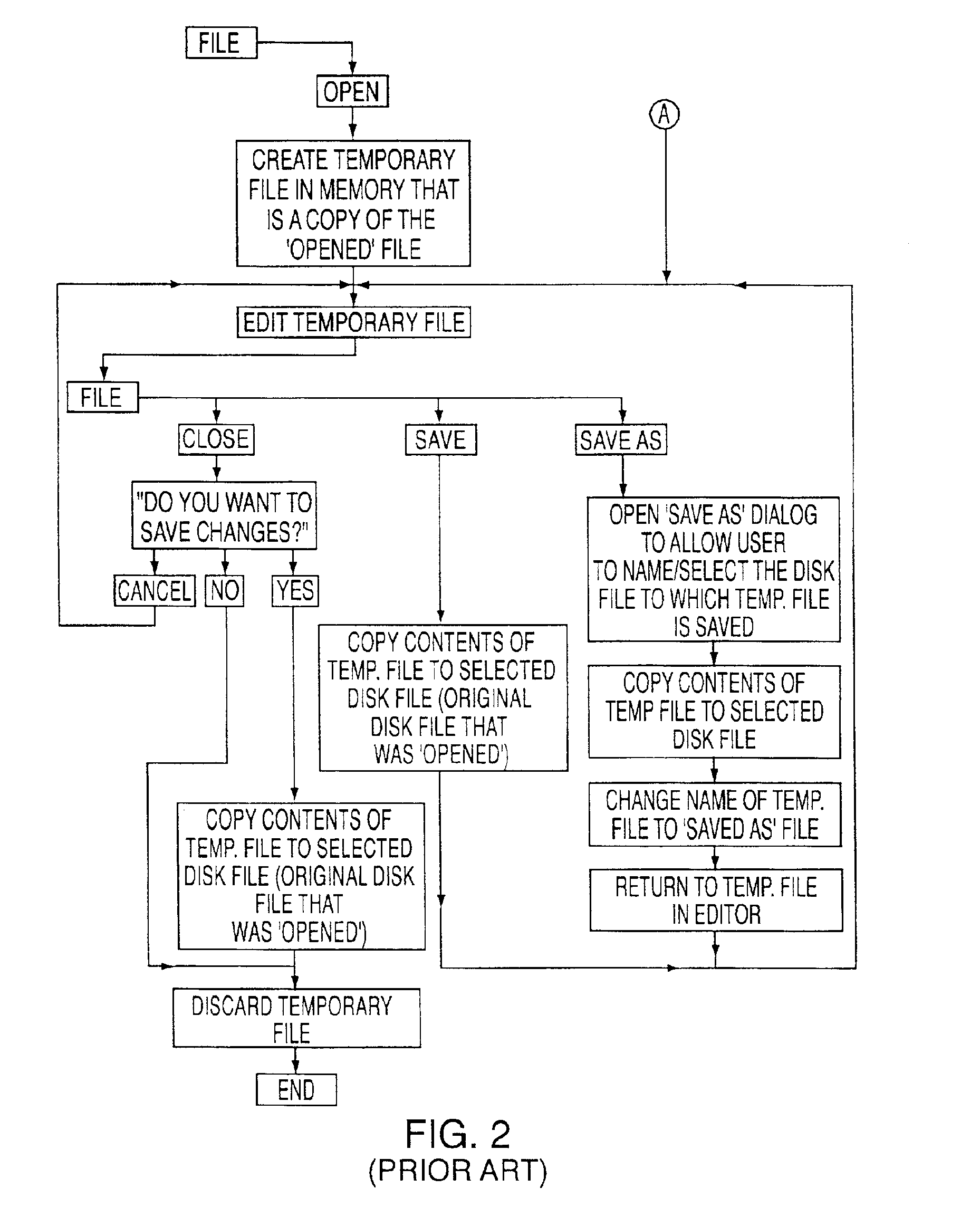
[0034]FIG. 2 shows a flowchart of the basic functionality and menu functions of a prior art file-based editor in the mode where an existing file is being edited.

[0035]FIG. 3 shows an electronics assembly engineering system (having a CPU and data storage) coupled to an human machine interface (HMI) and to an electronics assembly system in accordance with the present invention.

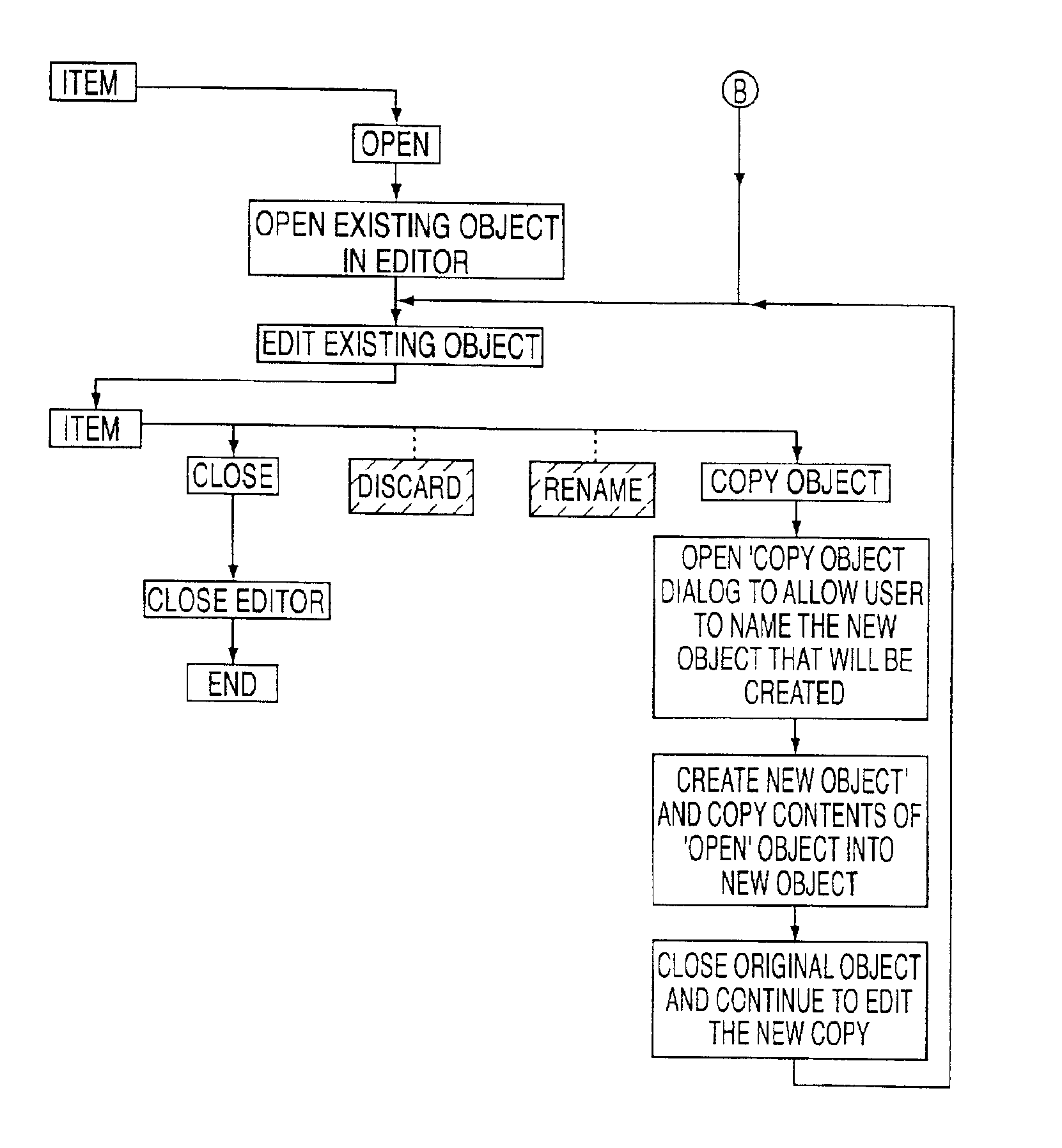
[0036]FIG. 4 shows a flowchart of the basic functionality and menu functions of an editor according to the present invention in the mode where a new object is being created.

[0037]FIG. 5 shows a flowchart of the basic functionality and menu functions of an editor according to the present invention in the mode where an existing object is being edited.

DETAILED DESCRIPTION OF THE INVENTION

[0038]As discussed in the Ba...


PUM


Abstract

The present invention provides novel naming and manipulation functions for user defined data structures in a data system using transaction service. In particular, in an electronics assembly engineering system having a computer subsystem in which user-defined data structures accessible to editor software have referential integrity and in which user modifications to the data structures during editing are made directly to the data structures rather than indirectly by way of a temporary file, the invention provides a method for permitting naming and manipulation of the data structures. The method includes the steps of (i) providing close, discard and rename functions for the data structures in the case where a newly-created data structure is being edited; (ii) providing close and copy functions for the data structures if an existing data structure is being edited; and (iii) excluding a save-as function for the data structures.

Description

CROSS-REFERENCE TO RELATED APPLICATIONS[0002]This application claims benefit, under 35 U.S.C. § 119(e), from U.S. Provisional Patent Application No. 60 / 188,964, filed Mar. 10, 2000.BACKGROUND OF THE INVENTION[0003]The present invention generally concerns electronics assembly engineering systems. In particular, the invention concerns methods of permitting naming and manipulation functions for data structures in data systems using transaction service within the environment of an electronics assembly engineering system. In particular, the invention concerns an electronics assembly engineering system having a computer subsystem incorporating computer-readable media for performing the methods and functions of the invention.[0004]Electronics assembly engineering systems for industrial applications require complex and sophisticated subsystems to control performance of each system and to account for changes in the application parameters and the industrial environment. Control has traditiona...

Claims


Application Information

Patent Timeline
IPC IPC(8): G06F17/00G06F17/30G06F12/00G06F9/44G06F9/46G06F40/143
CPCG06F9/466G06F17/24G06F17/2247Y10S707/99953G06F40/166G06F40/143
Inventor STOCKLEY, BRIAN HENRY
Owner SIEMENS ELECTRONICS ASSEMBLY SYST LLC
Learn More