
Method for producing a piezoelectric speaker

a piezoelectric speaker and piezoelectric technology, applied in the direction of piezoelectric/electrostrictive transducers, transducer types, electrical transducers, etc., can solve the problems of large peak dips in acoustic characteristics in a wide frequency range, conventional piezoelectric speakers have difficulty in reproducing sound in a low frequency range, etc., to prevent air from leaking

Inactive Publication Date: 2005-03-15
PANASONIC CORP
View PDF33 Cites 15 Cited by
  • Summary
  • Abstract
  • Description
  • Claims
  • Application Information

AI Technical Summary

Benefits of technology

"The invention is about a piezoelectric speaker that can produce sound in a lower frequency range. The speaker includes a frame, vibrating plates, a piezoelectric element, and an edge to prevent air from leaking. The vibrating plates can have different weights, thicknesses, or physical properties from one another. The speaker system can include multiple speakers with different acoustic characteristics to complement each other. The technical effects of the invention include improved sound quality and reduced peak dips in the acoustic characteristics."

Problems solved by technology

For this reason, the conventional piezoelectric speakers have a problem in that a high sound pressure level is obtained in a high frequency range in which sound is reproduced at a relatively small amplitude, whereas a sufficiently high sound pressure level is not obtained in a low frequency range of about 1 kHz or less.
Accordingly, a sufficient compliance is not obtained.
As described above, the conventional piezoelectric speakers have a problem of having difficulty in reproducing sound in a low frequency range.
The conventional piezoelectric speakers have another problem that since a strong resonance mode is generated in a specific frequency, a large peak dip appears in the acoustic characteristics in a wide frequency range.

Method used


Image

  • Method for producing a piezoelectric speaker
  • Method for producing a piezoelectric speaker
  • Method for producing a piezoelectric speaker

Examples


Embodiment Construction

Hereinafter, the present invention will be described by way of illustrative examples with reference to the accompanying drawings.

1. Structure of Piezoelectric Speaker

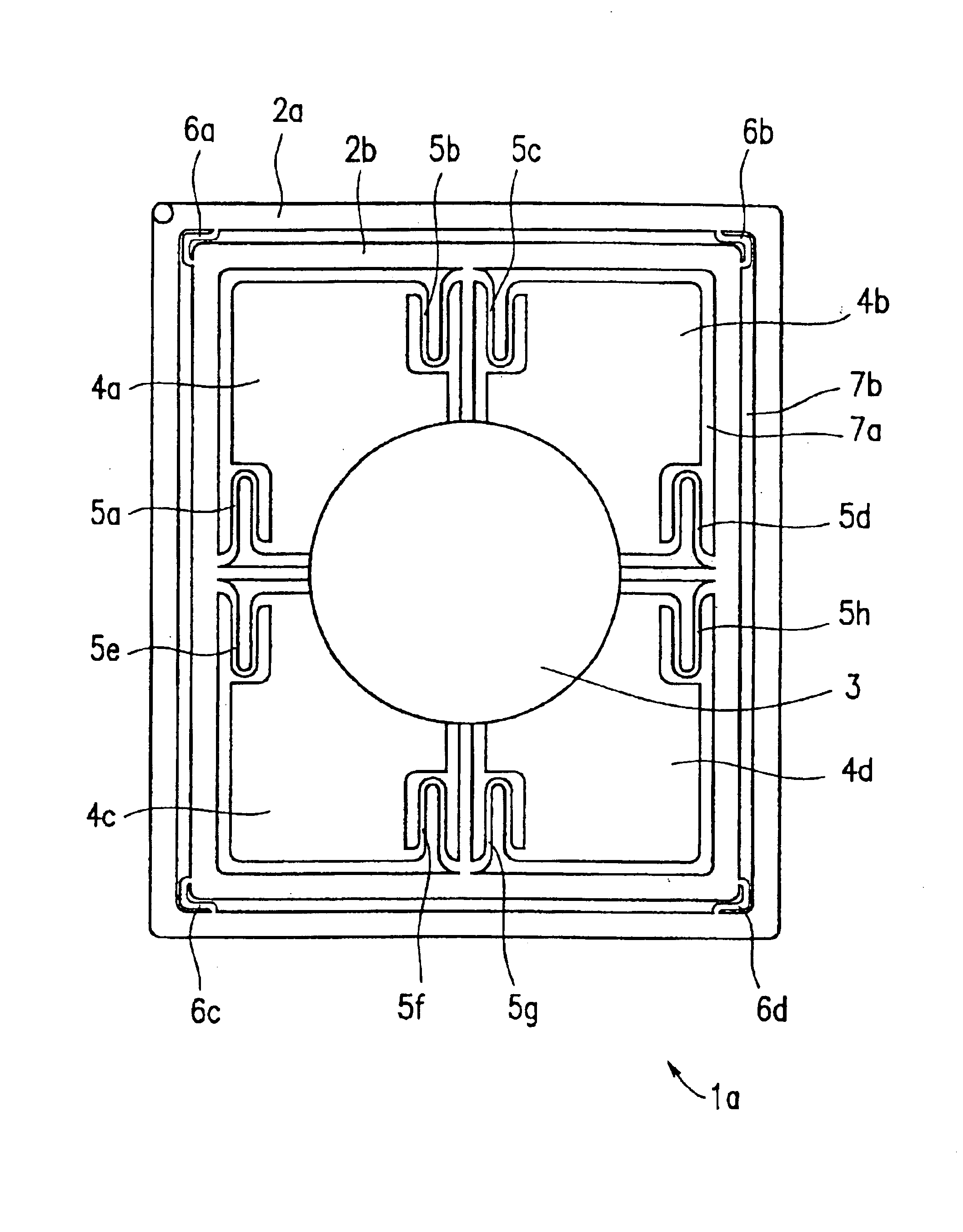
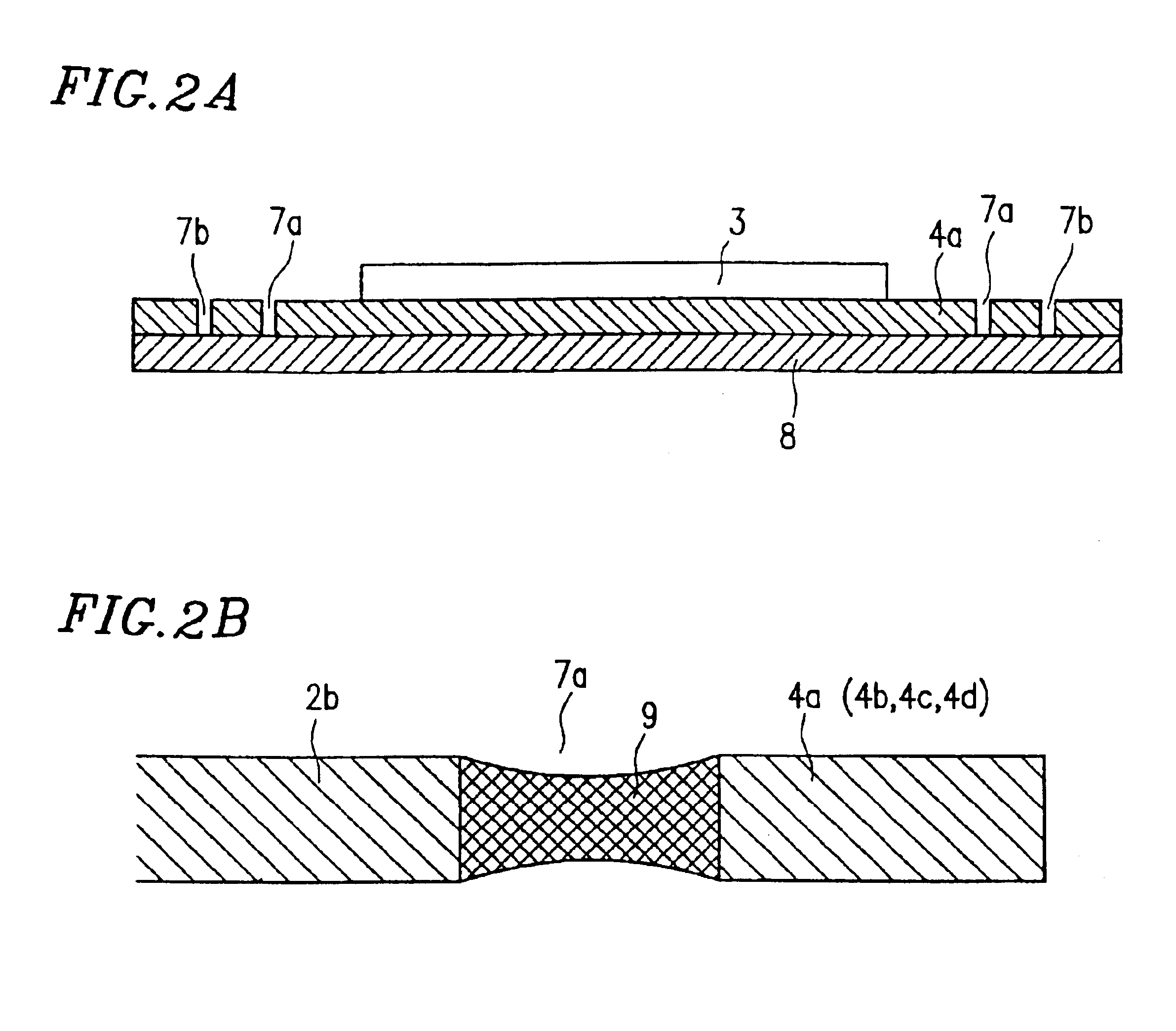
FIG. 1 is a plan view illustrating a structure of a piezoelectric speaker 1a in an example according to the present invention.

The piezoelectric speaker 1a includes an outer frame 2a, an inner frame 2b, vibrating plates 4a through 4d, and a piezoelectric element 3 for transmitting a vibration to the vibrating plates 4a through 4d.

The vibrating plate 4a is connected to the inner frame 2b via dampers 5a and 5b. The vibrating plate 4b is connected to the inner frame 2b via dampers 5c and 5d. The vibrating plate 4a is connected to the inner frame 2b via dampers 5e and 5f. The vibrating plate 4d is connected to the inner frame 2b via dampers 5g and 5h.

The inner frame 2b is connected to the outer frame 2a through dampers 6a through 6d. The outer frame 2a is secured to a securing element (not shown) of the piezoelectric speak...


PUM

PropertyMeasurementUnit
frequencyaaaaaaaaaa
voltageaaaaaaaaaa
distanceaaaaaaaaaa

Abstract

A piezoelectric speaker is manufactured by processing a plate to form a frame, a plurality of vibrating plates and a plurality of dampers. The plurality of dampers are connected to the frame and the plurality of vibrating plates so that each of the plurality of vibrating plates linearly vibrates. At least one piezoelectric element is arranged on the plurality of vibrating plates. An edge is formed for preventing air from leaking through a gap among the plurality of vibrating plates, the plurality of dampers, and the frame.

Description

BACKGROUND OF THE INVENTION1. Field of the InventionThe present invention relates to a piezoelectric speaker for use in, for example, audio equipment, a method for producing the same, and a speaker system including such a piezoelectric speaker.2. Description of the Related ArtAn audio reproduction mechanism of a piezoelectric speaker is based on planar resonance. Conventional piezoelectric speakers have a structure in which a peripheral portion of a vibrating plate is fixed to a frame. In such a structure, the amplitude of the vibrating plate is significantly reduced toward the peripheral portion of the vibrating plate. As a result, the vibration energy which can be transmitted to the air from the peripheral portion of the vibrating plate is significantly reduced. Such a vibrating plate characteristic is the same as that of the vibration surface of a percussion drum.For this reason, the conventional piezoelectric speakers have a problem in that a high sound pressure level is obtaine...

Claims


Application Information

Patent Timeline
Patent Type & Authority Patents(United States)
IPC IPC(8): H04R17/00
CPCH04R17/00Y10T29/49126Y10T29/4913Y10T29/42
Inventor OGURA, TAKASHIMURATA, KOUSAKU
Owner PANASONIC CORP
Learn More