
Numerical-control milling machine

a milling machine and numerical control technology, applied in the direction of metal-working holders, large fixed members, supporters, etc., can solve the problems of lack of versatility and use on a very small scal

Inactive Publication Date: 2005-03-15
O M V OFF MEC VENETE
View PDF31 Cites 41 Cited by
  • Summary
  • Abstract
  • Description
  • Claims
  • Application Information

AI Technical Summary

Benefits of technology

It is an object of the present invention to provide a numerical-control milling machine designed to eliminate the above drawbacks.

Problems solved by technology

Milling machines of the above type have the major drawback of lacking versatility, and so only being used on a very small scale.

Method used


Image

  • Numerical-control milling machine
  • Numerical-control milling machine
  • Numerical-control milling machine

Examples


Embodiment Construction

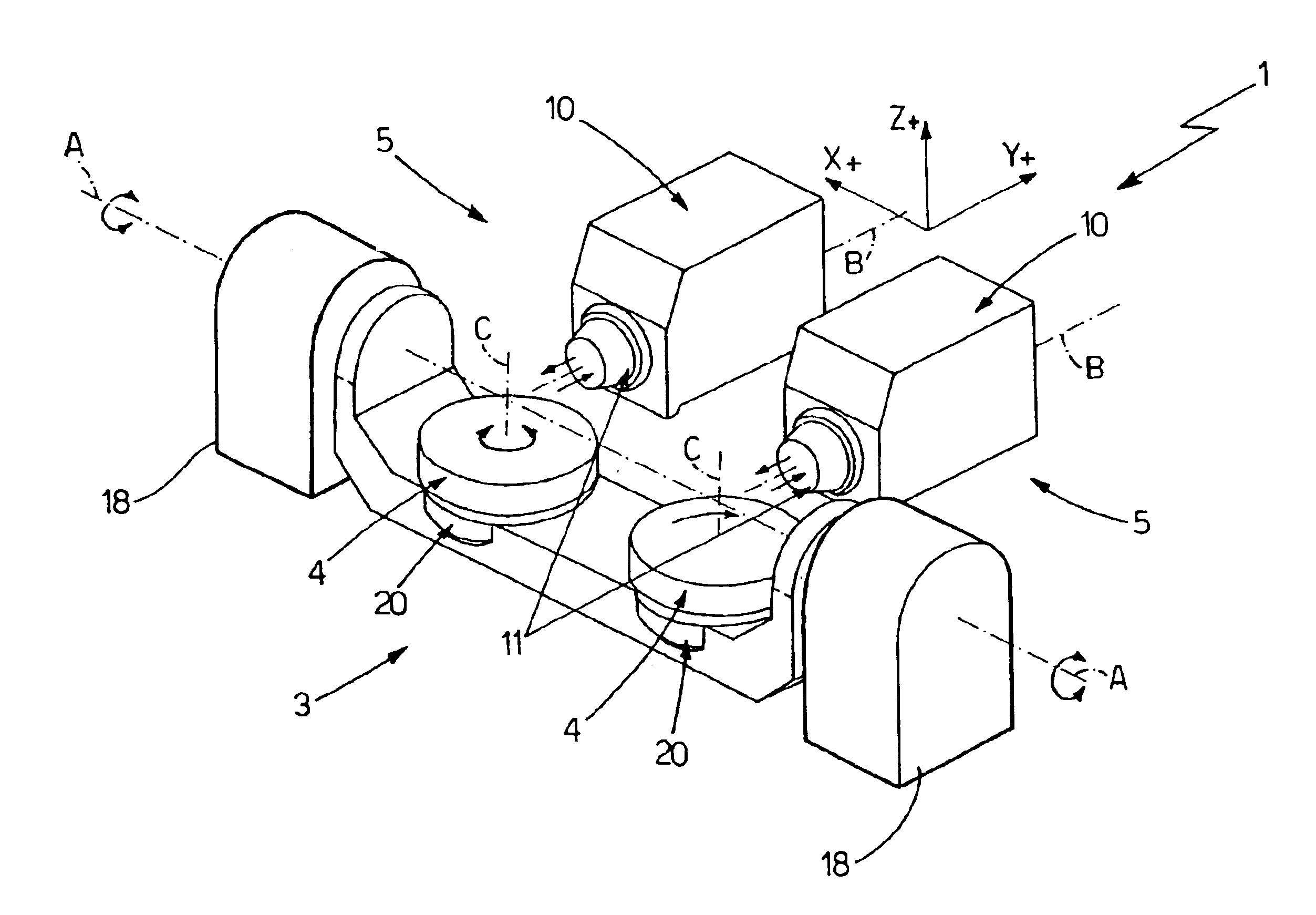
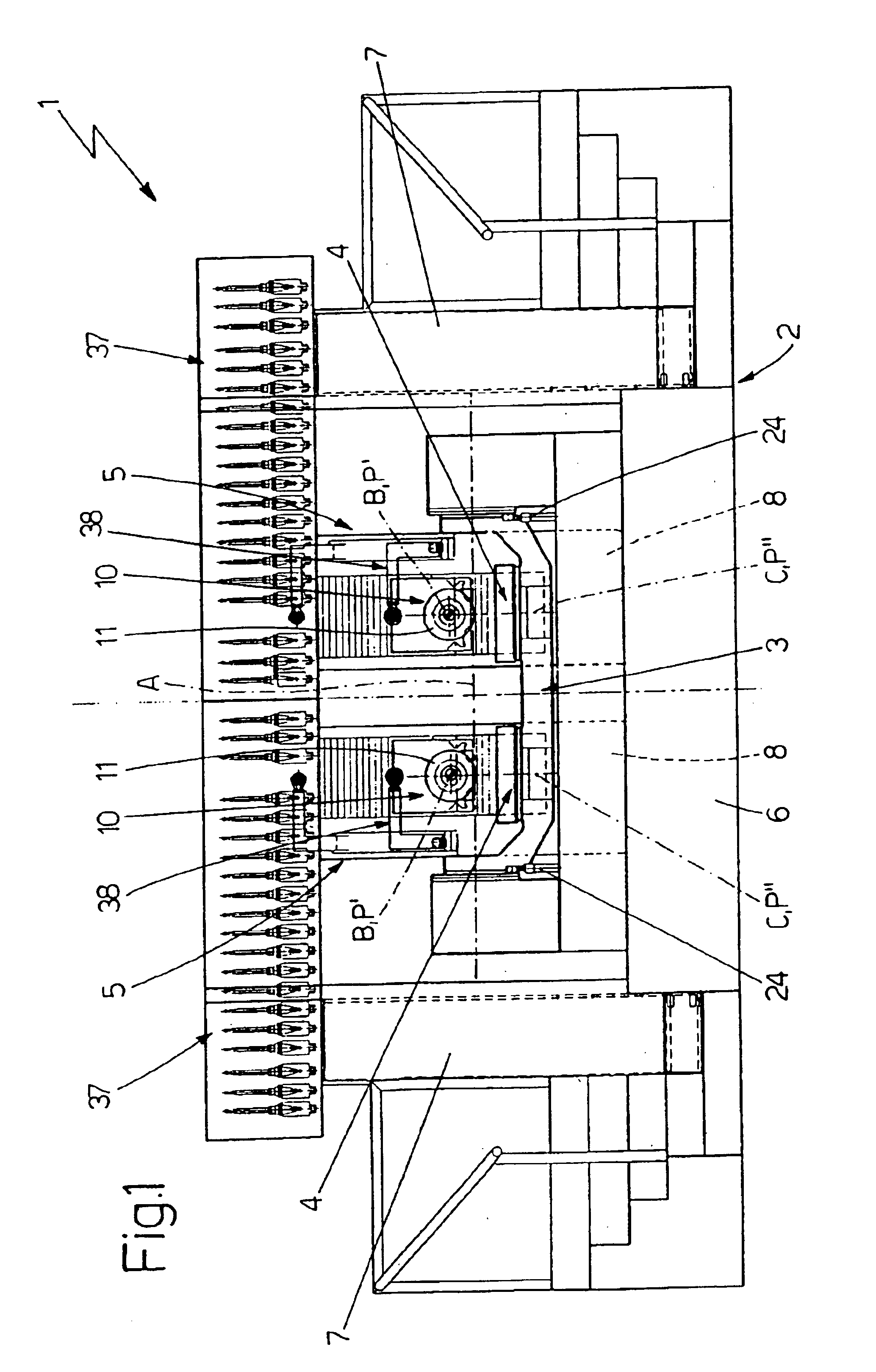
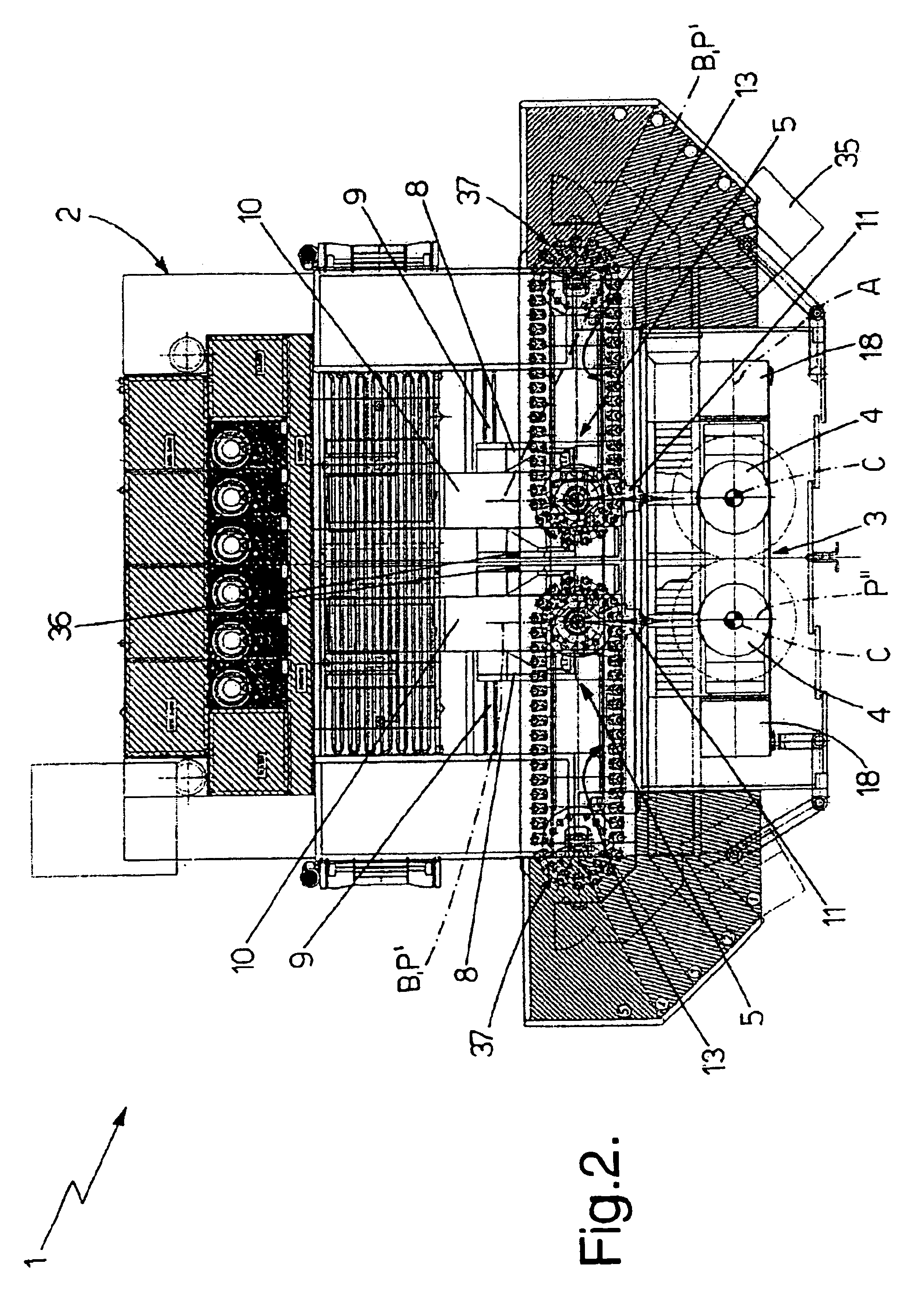
With reference to FIGS. 1-4, number 1 indicates as a whole a numerical-control milling machine which may be used to advantage for producing the blades and / or bladed stages of any type of gas turbine, or any three-dimensional part of complex structure.

Milling machine 1 comprises: a supporting frame 2; a rocking worktable 3 having two rotary platforms 4, each for accommodating a respective workpiece; and two independent work units 5, each of which is positioned facing a respective rotary platform 4 of worktable 3, and provides for machining the workpiece on the corresponding rotary platform 4 as described in detail later on.

More specifically, worktable 3 is substantially U-shaped, and is fixed at both sides to supporting frame 2 to oscillate about a horizontal axis A of rotation located over the bottom of the worktable where the two rotary platforms 4 are positioned; and the two workpieces are positioned on rotary platforms 4 so that their centers of gravity lie, when possible, along ...


PUM

PropertyMeasurementUnit
rotationaaaaaaaaaa
weightaaaaaaaaaa
gravityaaaaaaaaaa

Abstract

A numerical-control milling machine having a supporting frame; a worktable fitted to the supporting frame so as to oscillate about a substantially horizontal first axis of rotation, and in turn having two rotary platforms, each for accommodating a workpiece; and two independent work units, each of which is fitted movably to the supporting frame, alongside the worktable, is positioned facing a corresponding platform, and provides for machining the workpiece on the platform; the two work units selectively operating either asynchronously, to machine the workpieces fixed to the two platforms independently of each other, or synchronously to perform the same machining operations simultaneously on the workpieces fixed to the two platforms.

Description

The present invention relates to a numerical-control milling machine.More specifically, the present invention relates to a numerical-control, five-axis milling machine for producing gas-turbine blades, to which the following description refers purely by way of example.BACKGROUND OF THE INVENTIONAs is known, numerical-control milling machines currently used for producing gas-turbine blades comprise a supporting frame; a rocking worktable fixed to the supporting frame to oscillate about a horizontal axis of rotation over the worktable; and a work unit having a toolspindle movable in space to perform any desired milling operation.The work unit normally comprises an upright fitted to the supporting frame to move in a horizontal direction parallel to the axis of rotation of the worktable; and a toolhead movable vertically, on command, along the upright, and which is normally equipped with an electrically operated horizontal spindle movable horizontally to and from the worktable in a dire...

Claims


Application Information

Patent Timeline
Patent Type & Authority Patents(United States)
IPC IPC(8): B23Q16/00B23Q1/25B23Q1/54B23Q11/08B23Q16/02B23Q39/00B23Q3/155B23Q39/04
CPCB23Q1/5437B23Q11/08B23Q16/02B23Q39/04B23Q3/15513Y10T409/305824B23Q2039/002Y10T408/3833Y10T29/5128Y10T409/309688Y10T409/305264Y10T29/5129Y10T409/307784Y10T409/30896Y10T409/307168Y10T408/545Y10T408/3806Y10T409/305656
Inventor PASQUETTO, FRANCO
Owner O M V OFF MEC VENETE
Learn More