Tool having a holder for mounting on a drive shaft

a technology of a drive shaft and a holder is applied in the field of tools, which can solve the problems of not always up to the high, excessive resilience, and relatively complicated structure of the tool, and achieve the effect of low cost and easy production

Inactive Publication Date: 2005-03-15
C & E FEIN
View PDF34 Cites 56 Cited by
  • Summary
  • Abstract
  • Description
  • Claims
  • Application Information

AI Technical Summary

Benefits of technology

It is a first object of the present invention to provide a tool that can easily be produced at lo

Problems solved by technology

However, the different known variants are connected with the disadvantage that they are not always up to the high stresses, whi

Method used


Image

  • Tool having a holder for mounting on a drive shaft
  • Tool having a holder for mounting on a drive shaft
  • Tool having a holder for mounting on a drive shaft

Examples


Embodiment Construction

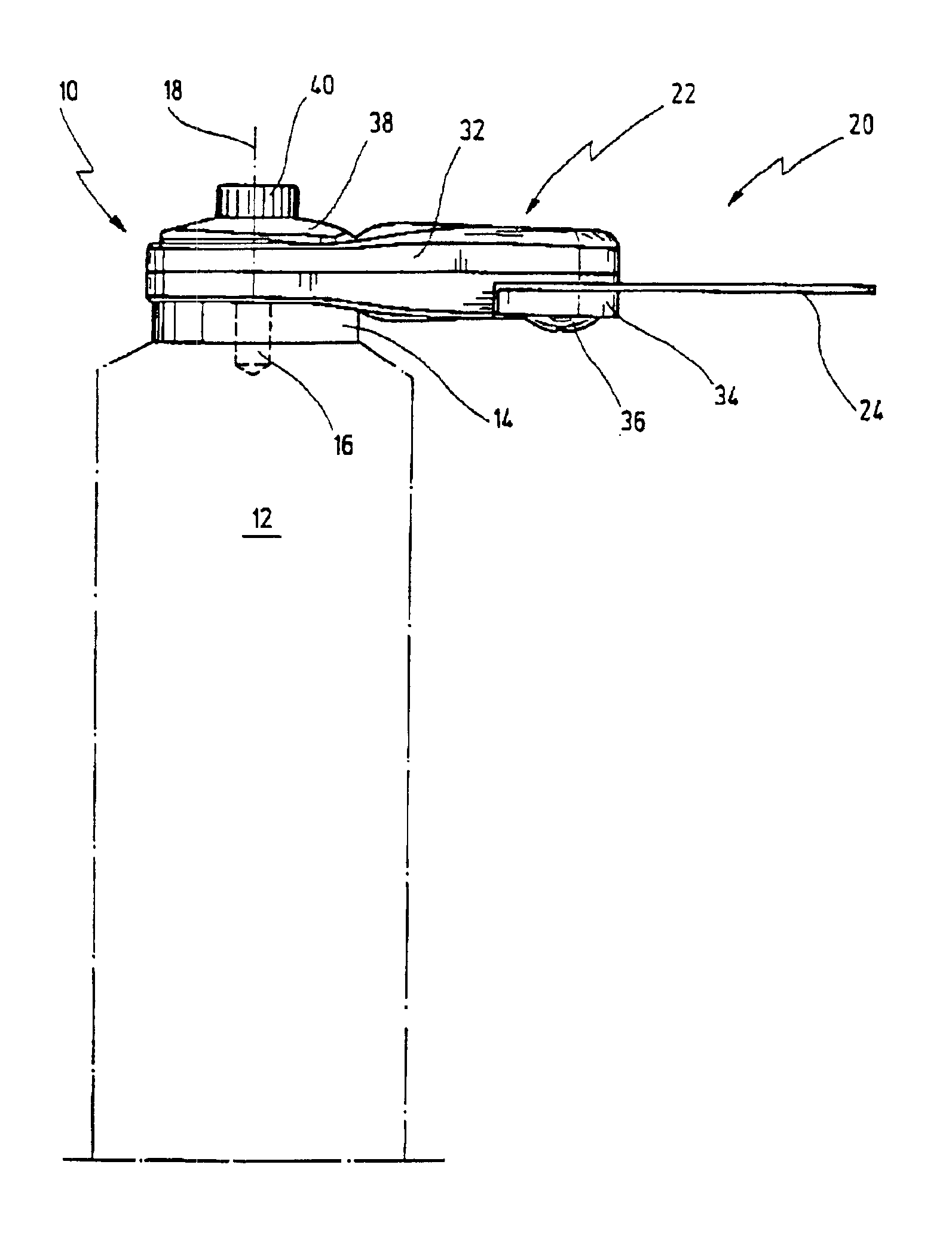
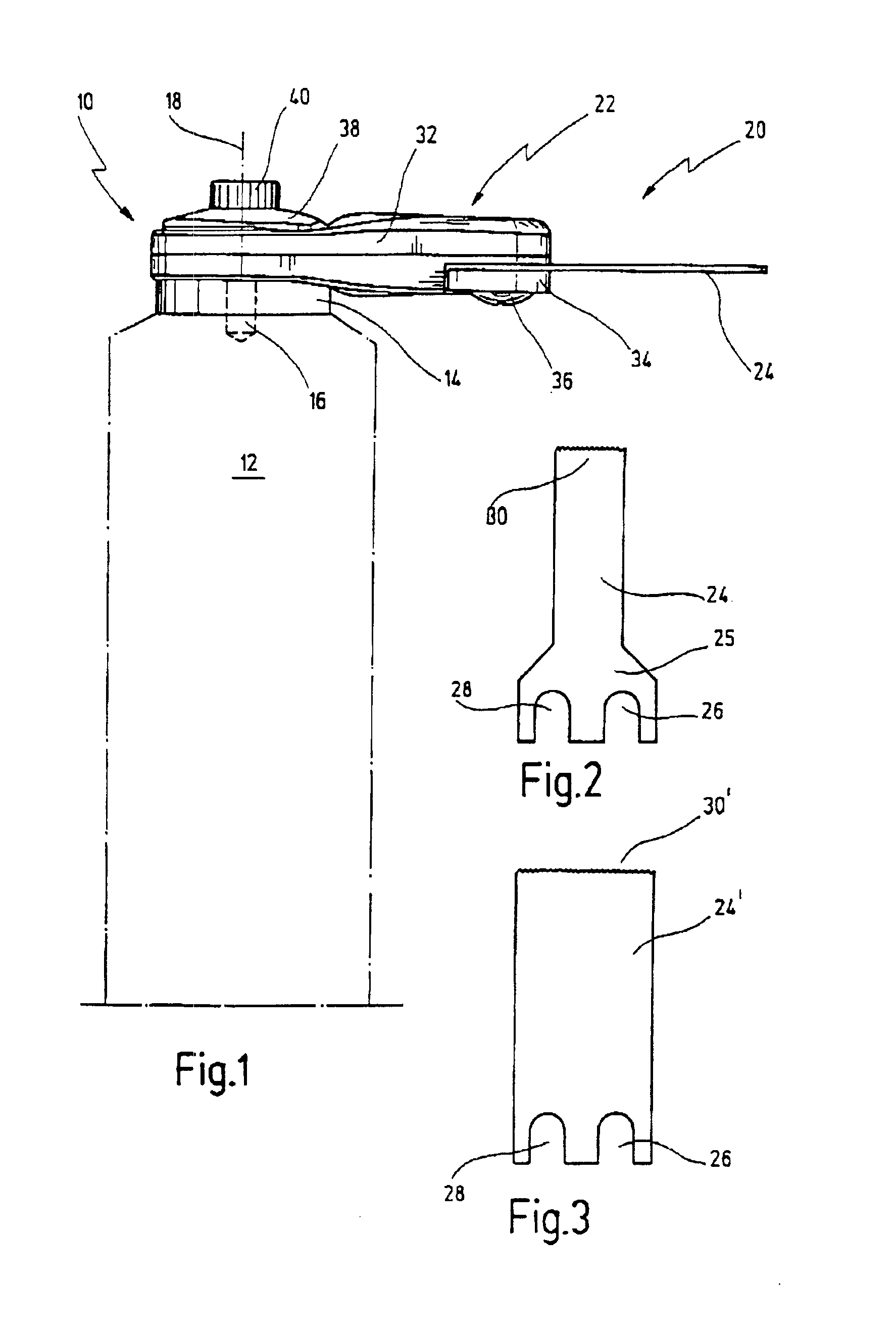
In FIG. 1, a power tool, shown in purely diagrammatic representation, is indicated by reference numeral 10.

The power tool 10 comprises, for example, an oscillating drive 12 which sets a drive shaft 14 in reciprocating oscillating movement about its longitudinal axis 18, at a small pivotal angle of, for example, 0.5-5 degrees and at a high frequency of, for example, about 5000 to 30000 oscillations per minute.

Oscillating drives of that kind are known and are employed in connection with a correspondingly shaped cutting knife, for example for cutting through an adhesive bead on a windscreen in cases where the windscreen must be exchanged because of a defect, for example. In addition, such tools which are driven in oscillating fashion, have been found to be of advantage for numerous other tasks for which the most diverse sawing tools of oblong, circular or partially circular shape, grinding tools of special shapes or cutting tools in the form of specially designed cutting knives are kno...


PUM


Abstract

A tool is disclosed having a holder provided with a mounting opening for mounting on a drive shaft, which may be driven in oscillating fashion, and having further a fixture for mounting a working element. The working element comprises at least two holding sections, spaced one from the other in tangential direction to the mounting opening, and wherein a mounting plate is provided which is engaged by releasable securing elements that coact with the holding sections for clamping the working element against the holder.

Description

BACKGROUND OF THE INVENTIONThe present invention relates to a tool having a holder provided with a mounting opening for mounting it on a drive shaft, which preferably can be driven in oscillating fashion, and having further a fixture for mounting a working element.The invention further relates to a holder and a working element for such a tool.A tool of this kind has been known from EP 0 339 357 B1 which discloses a cutting knife, especially for separating joint seals or insulating elements employed on glass panes, with a holder for mounting it detachably on the drive shaft that can be driven in oscillating fashion. To this end, the holder comprises a mounting opening that can be positively connected to a correspondingly shaped connecting piece of the drive shaft. The cutting or working element can be connected to the holder either directly or via an adapter element. By using such a split structure of the tool, it is intended to permit the tool to be produced at lower cost.However, t...

Claims


Application Information

Patent Timeline
IPC IPC(8): B26B7/00B23D51/14
CPCB24B23/04B26B7/00B24B27/08
Inventor POLLAK, ROLAND
Owner C & E FEIN
Why Eureka
Try Eureka