Tire having longitudinally extending smaller grooves formed in the walls of a groove

a technology of groove walls and grooves, applied in the field of tires, can solve the problems of increasing the surface area of grooves and disturbing the improvement of anti-hydroplaning performance, and achieve the effect of excellent wet performance and high hydroplaning occurrence ra

Inactive Publication Date: 2005-03-15
BRIDGESTONE CORP
View PDF17 Cites 24 Cited by
  • Summary
  • Abstract
  • Description
  • Claims
  • Application Information

AI Technical Summary

Benefits of technology

In order to confirm the effects of the invention, there were prepared a plurality of tires of a size PSR205 / 55R16 to compare the anti-hydroplaning performances.
, there were prepared a plurality of tires of a size PSR205 / 55R16 to compare the anti-hydroplaning performances.
All the following test tires is provided with a pattern having a center rib 30, second ribs 32 and blocks 34, as shown in FIG. 23.
The evaluations were determined in terms of the hydroplaning occurrence rates and were exponentially expressed by setting the tire a to 100. It is expressed that the larger numerical value indicates the higher hydroplaning occurrence rate and the more excellent wet performance.
TABLE 122 (Triangle)22 (Stepped)Wet Perf.D (mm)P (mm)Y (mm)X (mm)(Exponent)Tire a100Tire b0.30.3110Tire c0.30.4105Tire d0.30.5100Tire e0.30.6 92Tire f0.20.3115Tire g0.40.3105Tire h0.50.3100Tire i0.60.3 94Tire j0.30.3107Tire k0.40.4101Tire l0.30.3107Tire m0.1250.480.130.46104Tire n0.1660.500.180.46102Tire o0.1980.510.220.46 98Tire p0.1600.4400.180.4106Tire q0.1700.630.180.6 96Tire r0.30.3103

Problems solved by technology

However, the various experiments and investigations of the above-specified proposals have revealed: that the proposals (a), (b), (c) and (g) were encountered by the problem of a raised resistance, that the proposals (d) and (e) were adversely affected by the turbulences in the flow by the sipes in the grooves thereby to increase the resistance; and that the proposal (f) had too large projections to control the flow and increased the groove surface areas to raise the resistance.
In this case, the improvement in the anti-hydroplaning performances is rather disturbed by the excessively large pitch P of the smaller grooves.

Method used


Image

  • Tire having longitudinally extending smaller grooves formed in the walls of a groove
  • Tire having longitudinally extending smaller grooves formed in the walls of a groove
  • Tire having longitudinally extending smaller grooves formed in the walls of a groove

Examples


first embodiment

A first embodiment of the tire of the invention will be described with reference to FIGS. 1 to 4.

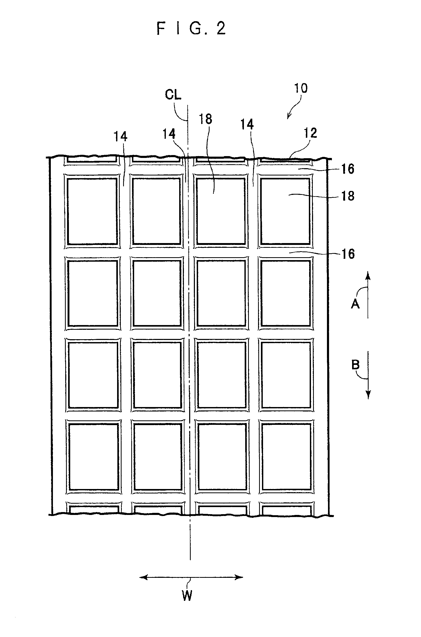
As shown in FIG. 2, a tire 10 is provided at its tread 12 with a plurality of blocks 18 which are defined by a plurality of circumferential grooves 14 extending in the tire circumferential directions (i.e., in the direction of arrow A and in the direction of arrow B) and a plurality of transverse grooves 16 intersecting those circumferential grooves 14.

The tire 10 of this embodiment has an internal structure identical to that of the normal (pneumatic) tire so that the description on the internal structure will be omitted. Here, the tire 10 of this embodiment is a pneumatic tire but could be applied to a tire (e.g., a solid rubber tire) other than the pneumatic tire.

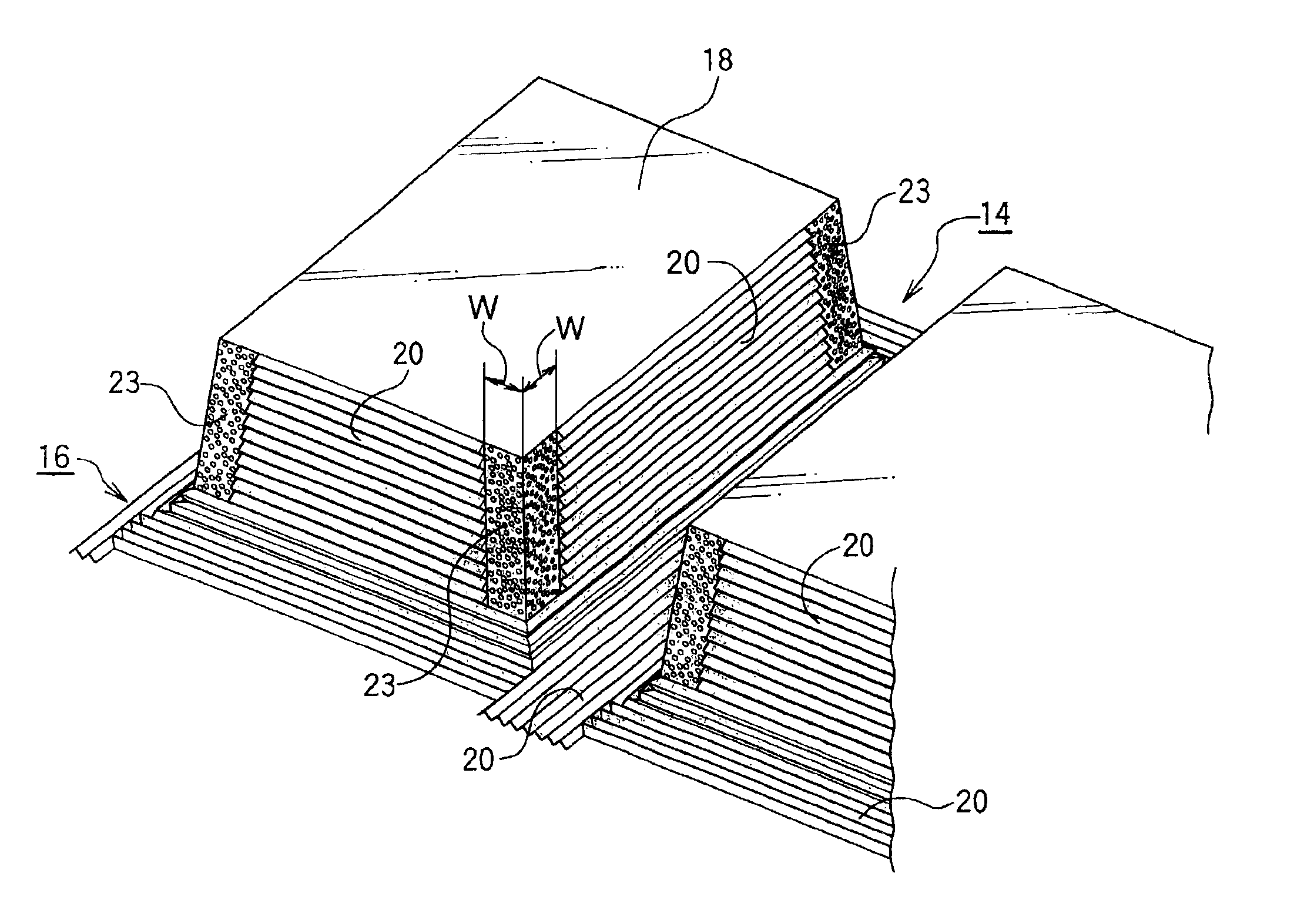
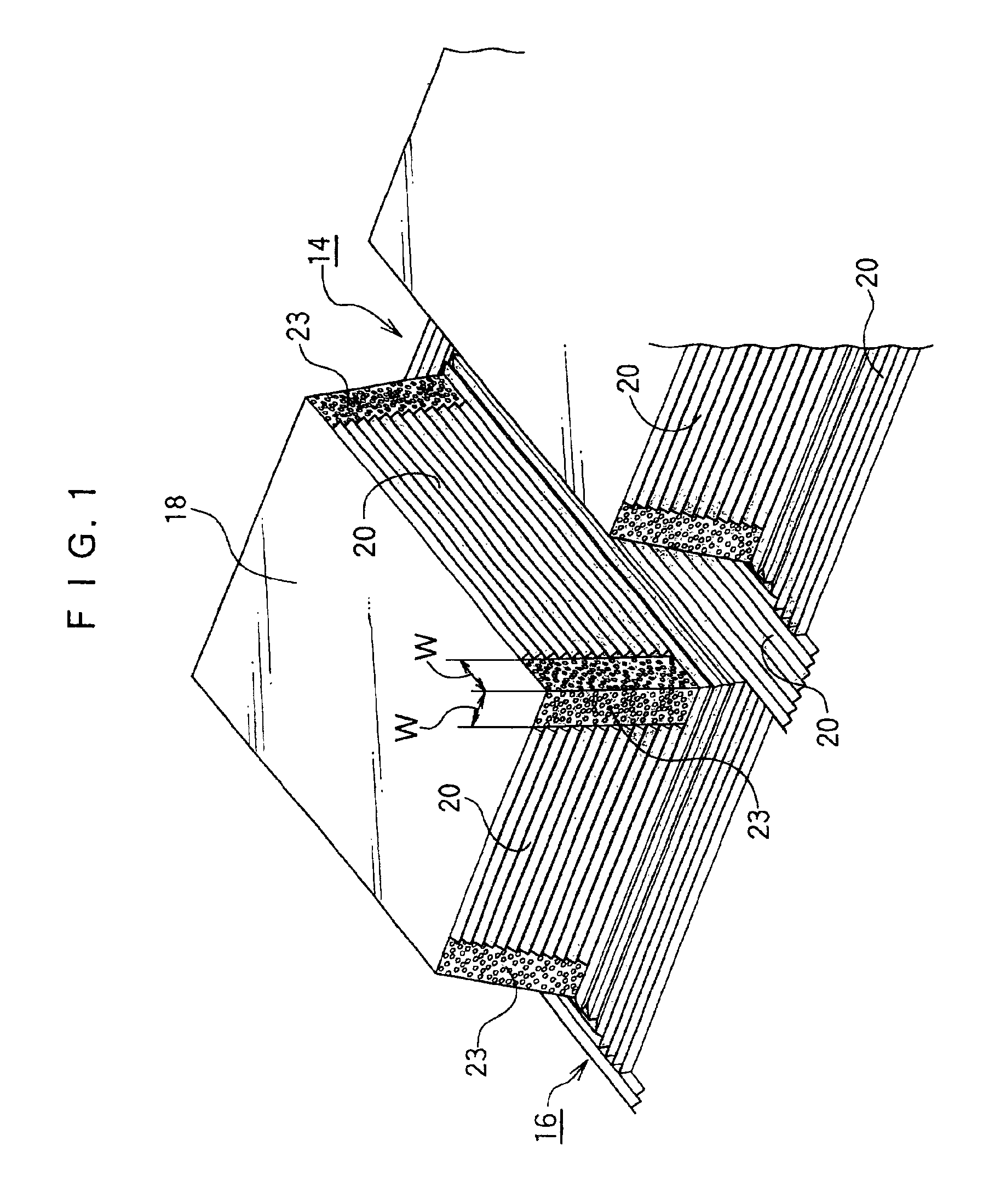
As shown in FIG. 1, riblets 20 are formed individually on the side and bottom walls of each circumferential groove 14 and on the side and bottom walls of each transverse groove 16.

In the riblets 20 of this embodiment, as shown...

second embodiment

A tire according to a second embodiment of the invention will be described with reference to FIG. 5. Here is omitted the description of the same components as those of the foregoing embodiment by designating the components by the common reference numerals.

In the tire 10 of this embodiment, the turbulence generating zone 23 is provided at the groove sides on the tread surface side of the predetermined width W, as shown in FIG. 5, in addition to the confluence between the circumferential groove 14 and the transverse groove 16.

(Actions)

When the tire 10 runs on a wet road surface so that the water on the road surface comes through the openings in the tread into the circumferential groove 14 and the transverse groove 16, turbulent flows are established in the water flowing in the vicinities of the grooves sides by the numerous pointed projections 24 near the openings. As a result, the separation of the coming water can be suppressed to allow the water on the road to flow with a lower res...

third embodiment

A tire according to a third embodiment of the invention will be described with reference to FIG. 6. Here is omitted the description of the same components as those of the foregoing embodiments by designating the components by the common reference numerals.

The tread pattern of the tire 10 of this embodiment is a rib pattern so that the tread 12 is provided exclusively with the circumferential grooves 14 having the riblets 20, as shown in FIG. 6.

In the tire 10 of this embodiment, the resistance experienced at the circumferential grooves 14 can be reduced as in the foregoing embodiments so that the wet performance can be improved better than the tire of the rib pattern of the prior art.


PUM


Abstract

A tire capable of reducing a resistance to a fluid in a groove to improve the wet performances. By forming smaller grooves (or riblets 20) having a depth set within a range of 0.01 to 0.5 mm at a pitch within a range of 0.01 to 0.5 mm in the walls of a circumferential groove and a transverse groove, more specifically, the resistance to the water flowing in the groove is reduced to improve the drainage efficiency of the groove. By arranging a turbulence generating zone having a number of pointed projections at the groove side faces at the confluence between the circumferential groove and the transverse groove, on the other hand, there is suppressed the separation of the water flow in the vicinity of the confluence. With these constructions, it is possible to improve the wet performances of the tire better than the prior art.

Description

BACKGROUND OF THE INVENTION1. Field of the InventionThe present invention relates to a tire and, more particularly, to a tire improved in the wet performances.2. Description of the Related ArtThe tire is provided in its tread with a plurality of grooves for achieving the wet performances.In order to improve the tire performances on a wet road surface, such as the anti-hydroplaning performances or the wet braking performances, it is necessary to improve the drainage of the grooves.For improving the drainage, it is necessary to reduce the resistance experienced between the fluid flowing in the grooves and the groove wall faces.Merely by roughing the groove wall faces, the surface area of the groove walls is increased to raise the resistance.As the tires having the rough groove wall faces, there have been proposed: (a) Japanese Utility Model Laid-Open No. 037708 / 1995; (b) Japanese Patent Laid-Open No. 201606 / 1992; (c) Japanese Patent Laid-Open No. 57704 / 1991; (d) Japanese Patent Laid-O...

Claims


Application Information

Patent Timeline
Patent Type & Authority Patents(United States)
IPC IPC(8): B60C11/13
CPCB60C11/13B60C2011/1231B60C2011/133Y10S152/902B60C2011/1338
Inventor OHSAWA, YASUO
Owner BRIDGESTONE CORP
Why Eureka
Try Eureka