Electrostatic spray device

a spray device and electrostatic technology, applied in the direction of electrostatic spraying apparatus, burners, liquid supply arrangements, etc., can solve the problems of difficult and/or uneconomical to manufacture the nozzle pathway and its vicinity for mass production, separation of liquid composition per se, and alteration of the functional performance expected by the liquid composition

Inactive Publication Date: 2005-03-15
THE PROCTER & GAMBLE COMPANY
View PDF11 Cites 27 Cited by
  • Summary
  • Abstract
  • Description
  • Claims
  • Application Information

AI Technical Summary

Benefits of technology

[0025]wherein the high voltage electrode comprises an antenna for facilitating flow of the liquid composition in the nozzle pathway; the antenna projecting at substantially the center of the nozzle pathway and having a basal diameter of from about 0.5 mm to about 3 mm, and a height of from about 0.

Problems solved by technology

Separation of the liquid composition per se is disadvantageous for the user, as it may alter the functional performance expected by the liquid composition.
While these methods are successful in providing electrostatic spray devices that are

Method used


Image

  • Electrostatic spray device
  • Electrostatic spray device
  • Electrostatic spray device

Examples


examples

[0140]The following examples further describe and demonstrate embodiments within the scope of the present invention. The examples are given solely for the purpose of illustration and are not to be construed as limitations of the present invention, as many variations thereof are possible without departing from the spirit and scope of the invention. Where applicable, ingredients are identified by chemical or CTFA name, or otherwise defined below.

examples 1-2

Device Examples 1-2

Example 1

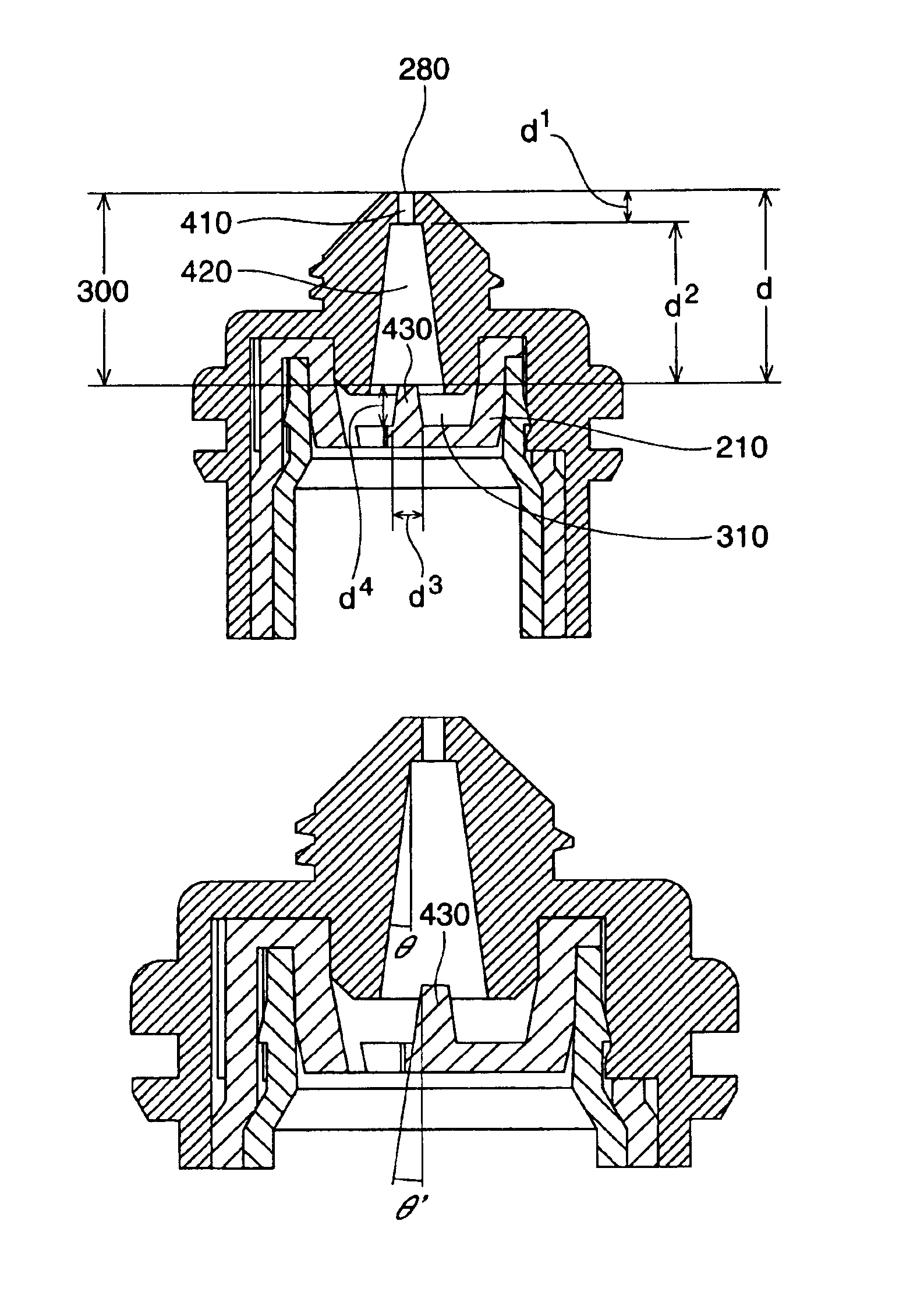
[0141]An electrostatic spraying device having the configurations of FIG. 4A with the following dimensions where made: d=8.98 mm, d2=7.46 mm, d3=1.50 mm, d4=2.05 mm.

example 2

[0142]An electrostatic spraying device having the configurations of FIG. 4C with the following dimensions where made: d=7.19 mm, d2=5.67 mm, d3=3.56 mm, d4=3.84 mm.


PUM


Abstract

An electrostatic spraying device being configured and disposed to electrostatically charge and dispense a liquid composition from a supply to a point of dispersal, wherein the device comprises:
    [0002]
  • a reservoir configured to contain the supply of liquid composition;
  • [0003]
  • a nozzle to disperse the liquid composition, the nozzle being disposed at the point of dispersal;
  • [0004]
  • a channel disposed between the reservoir and the nozzle, wherein the channel permits the electrostatic charging of the liquid composition upon the liquid composition moving within the channel;
  • [0005]
  • a high voltage power supply electrically connected to the power source; and
  • [0006]
  • a high voltage electrode electrically connected to the high voltage power supply, wherein a portion of the high voltage electrode is disposed between the reservoir and the nozzle, and wherein the high voltage electrode electrostatically charges the liquid composition within the channel at a charging location,
  • [0007]
  • wherein the nozzle pathway comprises an outlet path disposed adjacent to the nozzle, the outlet path having a diameter of from about 0.1 mm to about 1 mm and being a point or having a length of from about 0 mm to about 5 mm, and a main path disposed between the outlet path and the charging location, the main path having a diameter greater than the outlet path to about 5 mm and being straight or outwardly tapered towards the charging location at an angle of from about 0 to about 10 degrees.

Description

CROSS REFERENCE TO RELATED APPLICATION[0008]This application claims the benefit of U.S. Provisional Application No. 60 / 359,425, filed Feb. 25, 2002.FIELD[0009]The present invention relates to a portable electrostatic spray device designed for personal use, and a removable cartridge for the portable electrostatic spray device. More specifically, the present invention relates to improvements for providing a good spray quality while being safe for the user, and also for allowing the device and / or cartridge to be manufactured in a convenient, economical manner.BACKGROUND[0010]Portable electrostatic spray devices useful for spraying liquid compositions, and particularly those which utilize a removable cartridge, are known in patent publications such as WO 01 / 12336, WO 01 / 12335, US 2001-0020653A, US 2001-0038047A, US 2001-0020652A, and US 2001-0023902A. As recognized in the art, the design of an electrostatic spray device starts with identifying spray quality factors such as spray droplet...

Claims


Application Information

Patent Timeline
IPC IPC(8): B05B5/16B05B5/00B05B5/025
CPCB05B5/1691
Inventor SUMIYOSHI, TORUKADLUBOWSKI, BRYAN MICHAELWILSON, DAVID EDWARDBLYSTONE, RYAN NORRIS
Owner THE PROCTER & GAMBLE COMPANY
Why Eureka
Try Eureka