
Open face optical fiber array for coupling to integrated optic waveguides and optoelectronic submounts

Inactive Publication Date: 2005-03-15
ACT MICRODEVICES +1
View PDF49 Cites 59 Cited by
  • Summary
  • Abstract
  • Description
  • Claims
  • Application Information

AI Technical Summary

Benefits of technology

1) can be mated with an integrated optics chips having fiber alignment grooves for accurately locating a large number

Problems solved by technology

Coupling to optical fibers is difficult because the fibers must be accurately aligned with the waveguides.
In the device of Hakoun et al., the optical fibers must be placed in the V-grooves individually, a tedious task.
Individual placement of optical fibers in fiber aligment grooves is time consuming and tedious.

Method used


Image

  • Open face optical fiber array for coupling to integrated optic waveguides and optoelectronic submounts
  • Open face optical fiber array for coupling to integrated optic waveguides and optoelectronic submounts
  • Open face optical fiber array for coupling to integrated optic waveguides and optoelectronic submounts

Examples


Embodiment Construction

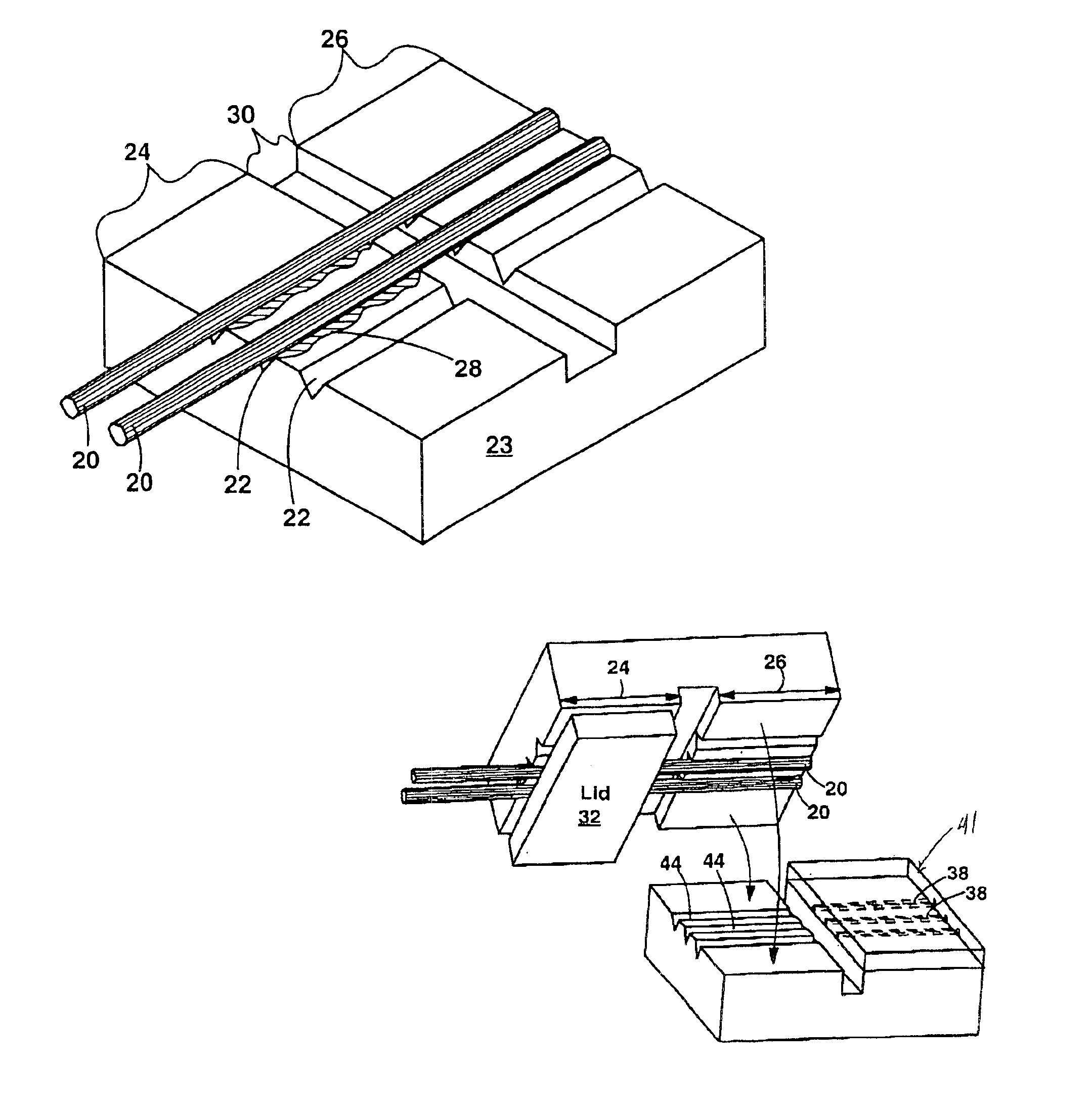
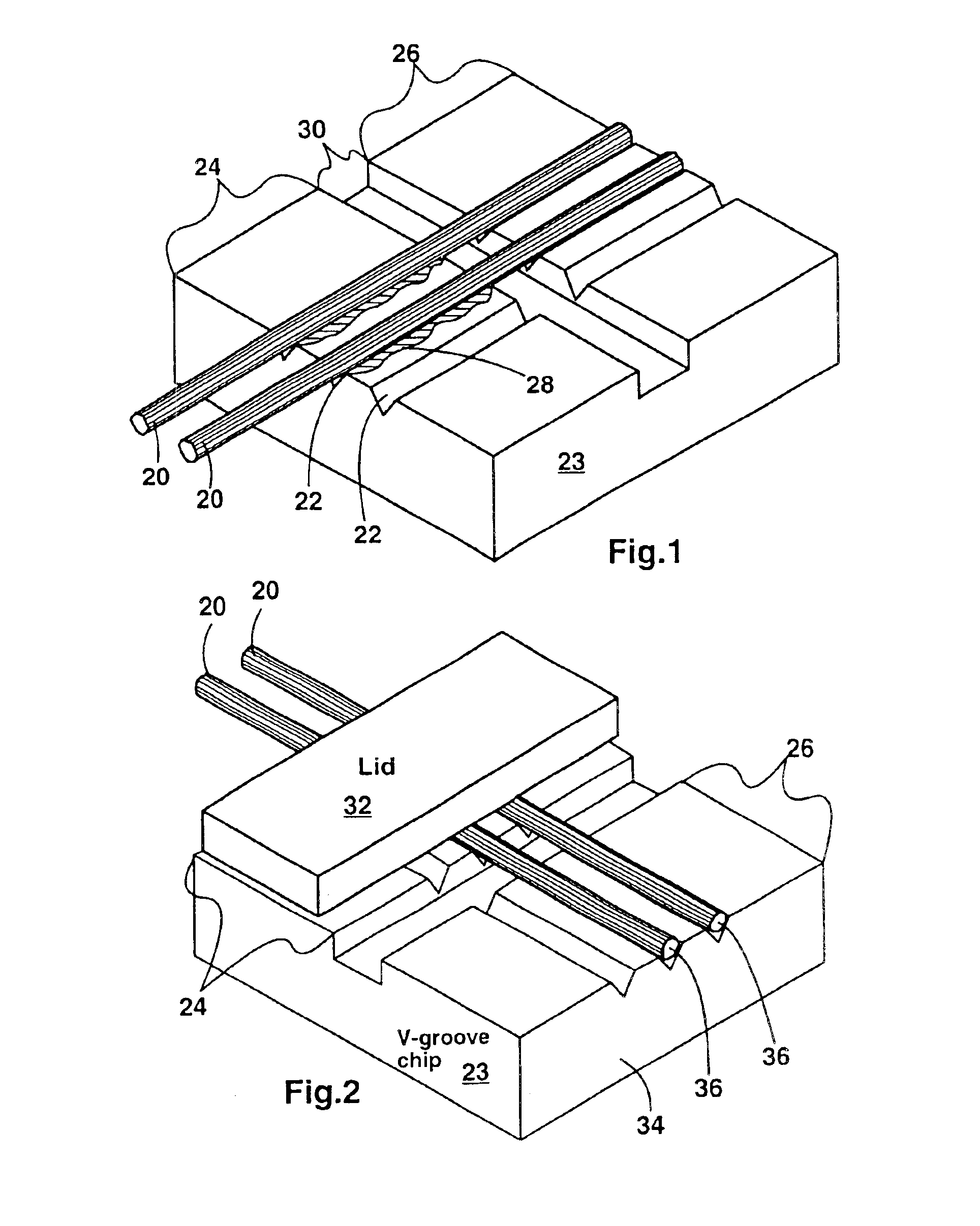
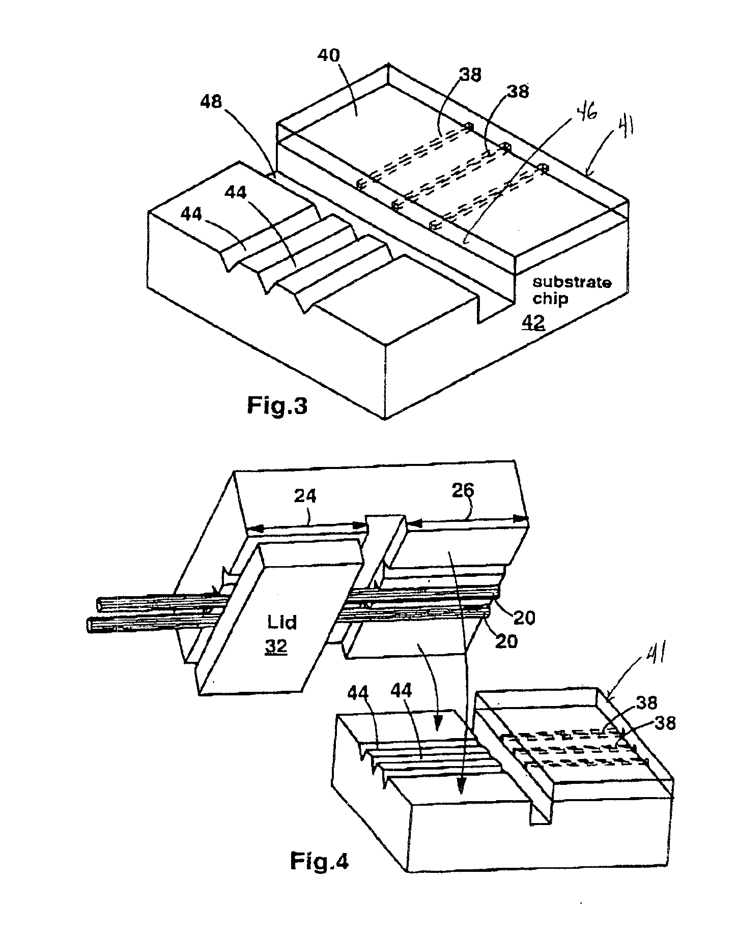
The present invention provides an open-face optical fiber array for coupling to substrates (e.g. integrated optics (IO) chips) having optical fiber alignment grooves. The open-face array has a V-groove chip with optical fibers disposed in the V-grooves. The V-groove chip has a rear portion where the fibers are bonded in the V-grooves (e.g. with glue), and a front portion where the optical fibers are NOT bonded to the V-grooves. The front portion has a front face that is preferably polished. The optical fibers extend from the rear portion. The optical fibers have endfaces that are preferably flush with the front face. A lid may be disposed on top of the rear portion where the optical fibers are bonded. In use, the array of the present invention is mated with an IO chip so that the unbonded optical fibers are pressed into the V-grooves of the IO chip. Since there is no glue on the optical fibers in the unbonded front portion, the fibers can be accurately aligned in the IO chip V-groov...


PUM


Abstract

An optical fiber array having a V-groove chip with a front portion and a rear portion. The optical fibers are disposed in the V-grooves. The optical fibers are bnonded (e.g. glued) to the V-groove chip in the rear portion of the chip. The optical fibers are not bonded to the front portion of the chip. Preferably, the optical fibers have endfaces that are flush with a front face of the chip. The optical fibers extend from the rear portion. In use, the optical fiber array is pressed against V-grooves of an integrated optics chip or optoelectronic submount. Since the optical fibers are not bonded to the front portion, they can move slightly to fit precisely into V-grooves of the IO chip or submount. Hence, optical fiber alignment is improved. Also, there is no danger of residual adhesive preventing close contact between the optical fibers and IO chip.

Description

FIELD OF THE INVENTIONThe present invention relates generally to structures for coupling to integrated optical devices. More particularly, the present invention relates to an optical fiber array having an open top face for coupling to integrated optics (IO) chips that have V-grooves for receiving optical fibers. The arrays of the present invention allow many optical fibers to be aligned and bonded to an IO chip simultaneously.BACKGROUND OF THE INVENTIONIntegrated optics (IO) chips have waveguides that typically must be coupled to optical fibers. Coupling to optical fibers is difficult because the fibers must be accurately aligned with the waveguides.In order to provide passive coupling alignment between optical fibers and IO waveguides, IO chips may have V-grooves aligned collinearly with the waveguides. An optical fiber disposed in the V-groove is automatically aligned with the IO waveguide.U.S. Pat. No. 5,123,068 to Hakoun et al. discloses an IO chip having V-grooves for fiber ali...

Claims


Application Information

Patent Timeline
IPC IPC(8): G02B6/36G02B6/42G02B6/30
CPCG02B6/30G02B6/3636G02B6/423G02B6/3652G02B6/3692G02B6/3696
Inventor STEINBERG, DAN ASHERRER, DAVID WDAUTARTAS, MINDAUGAS F
Owner ACT MICRODEVICES
Learn More