
Revetment block and mat

a technology of revetment blocks and mats, applied in the field of revetment blocks, can solve the problems of difficult replacement of cable or rope, block prone to vertical lifting forces, and cable fraying and breaking,

Inactive Publication Date: 2005-03-15
CONTECH ENGINEERED SOLUTIONS
View PDF19 Cites 27 Cited by
  • Summary
  • Abstract
  • Description
  • Claims
  • Application Information

AI Technical Summary

Benefits of technology

[0012]It is an even further objective of this invention to provide a revetment block which may connect with adjacent blocks of a revetment mattress by rope or cable to inhibit upward hydraulic thrust.
[0013]It is still an even further objective of this invention to provide a revetment block having at least one dome which slows the velocity of water passing above the revetment mat.

Problems solved by technology

This problem also exists in the U.S. Pat. No. 5,779,391, issued to Knight.
Without cabling extending through the revetment mat, the blocks would also be susceptible to vertical lifting forces.
However, often the cable may fray and break due to corrosion, rot, marine organisms and the like.
Once the revetment mat is positioned in a waterway it is very difficult to replace the cable or rope.
Moreover, it is difficult to remove the revetment mat from the waterway since the cables generally support the mattress during lifting.

Method used


Image

  • Revetment block and mat
  • Revetment block and mat
  • Revetment block and mat

Examples


Embodiment Construction

[0035]The Revetment Block

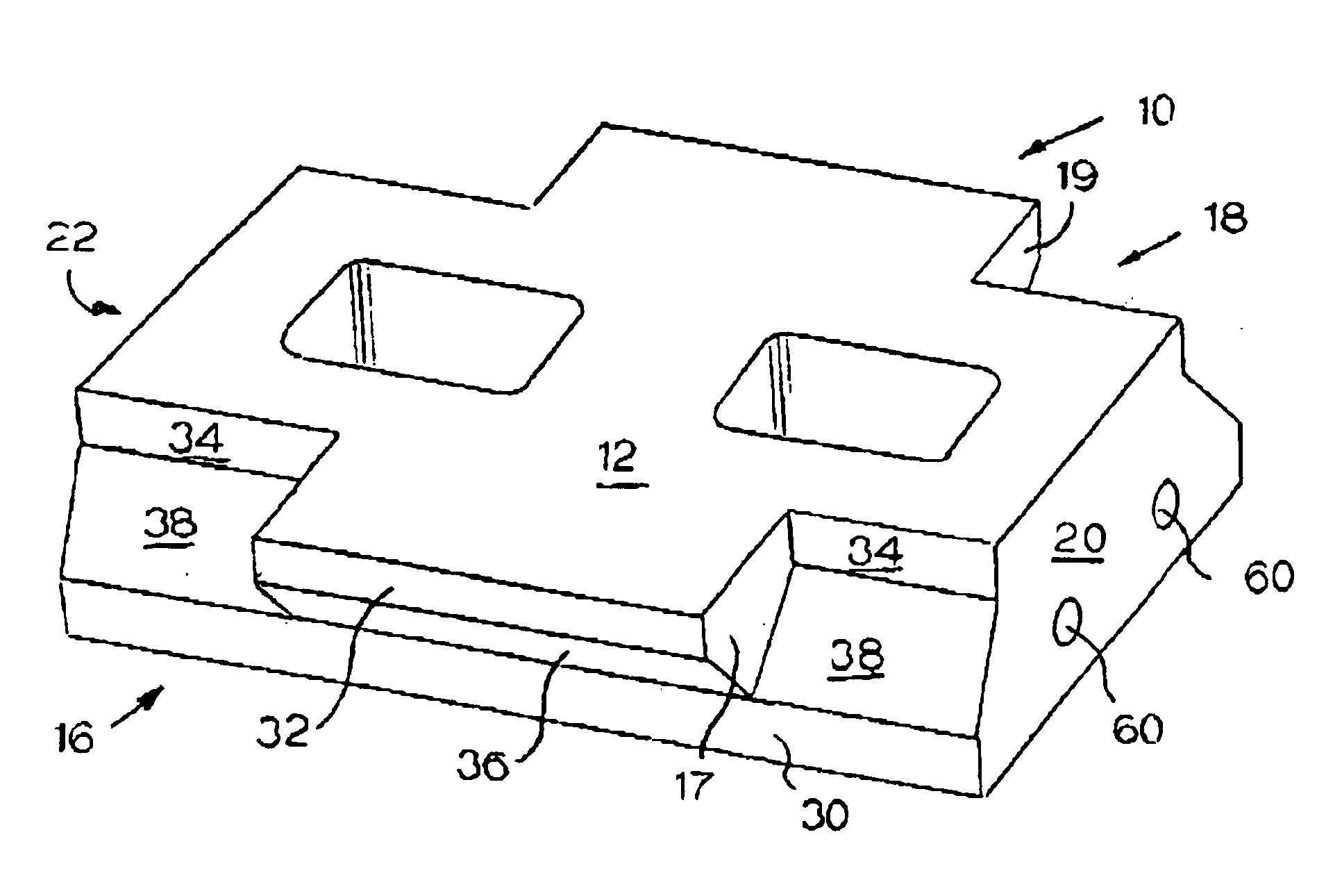
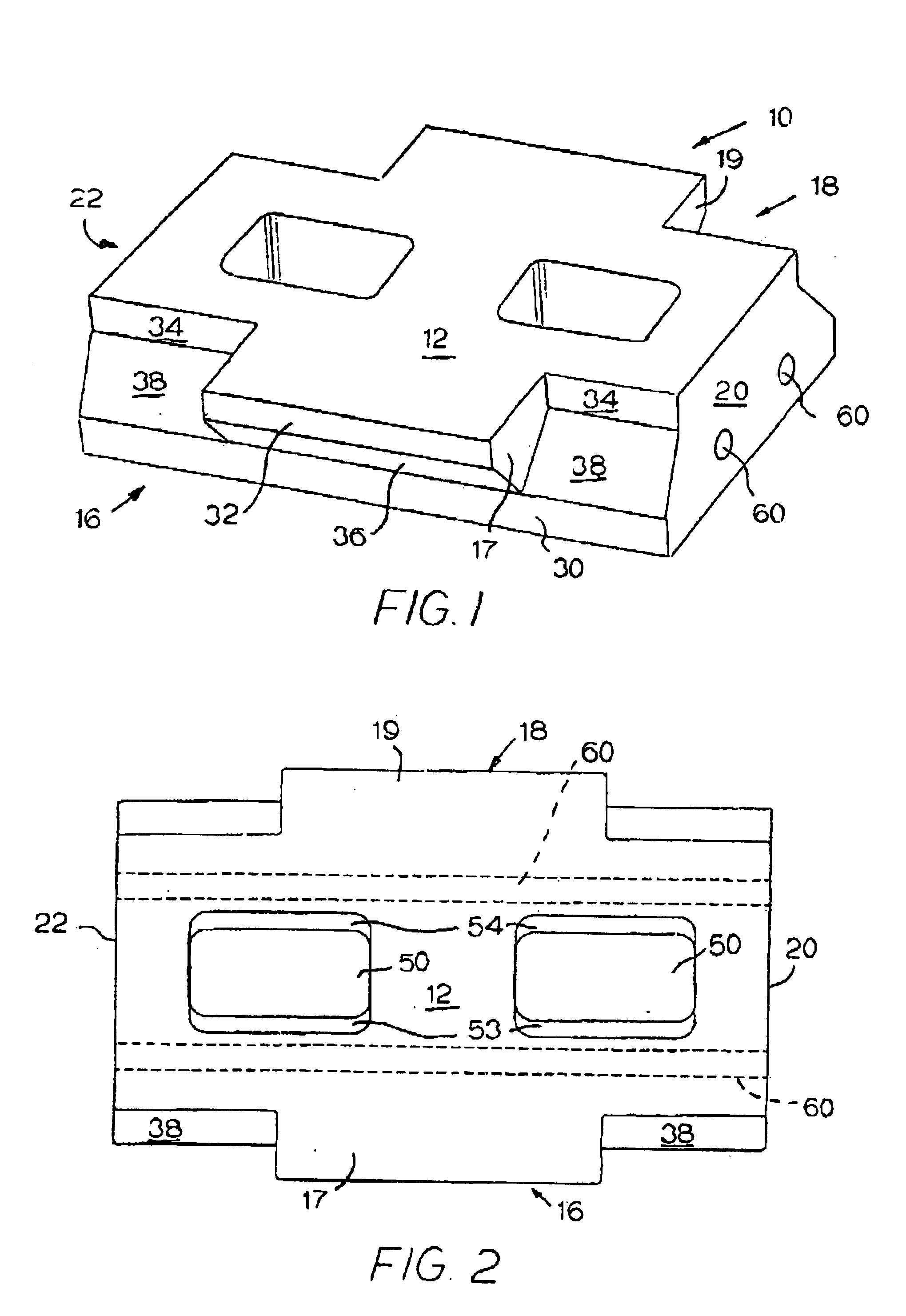
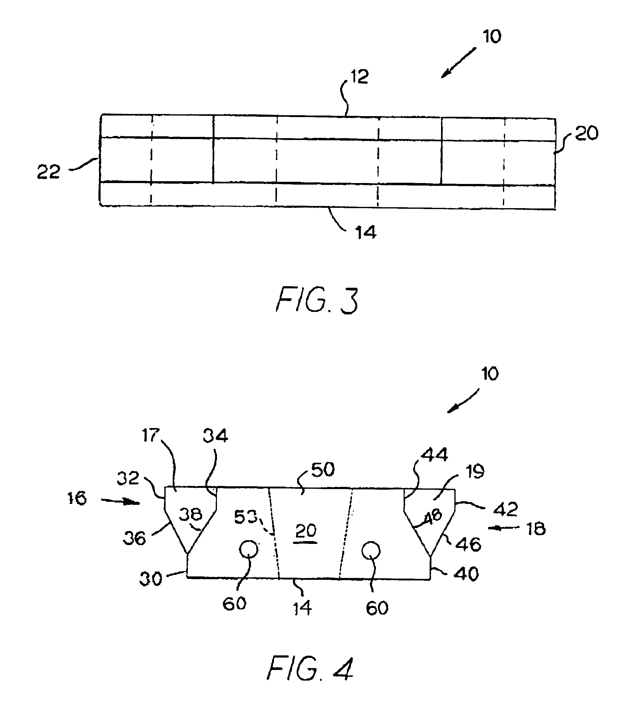
[0036]The present invention will now be described in conjunction with the drawings, referring initially to FIG. 1, a revetment block 10 is shown. The revetment block 10 is substantially rectangular in shape but may be any other desirable shape. The revetment block 10 may be formed from precast concrete according to a first embodiment of the present invention and preferably has dimensions of about 18 inches×10 inches. Additionally, the height of the block may vary depending on the application and desired hydraulic characteristics, but is generally between about 2.75 inches and 9.5 inches. However, these dimensions may vary depending on the desired application and hydraulic characteristics. For example, when larger hydrodynamic forces are involved, the height of the block 10 may be increased.

[0037]Referring now to FIGS. 1-4, the revetment block 10 has a substantially planar upper or top surface 12 and lower or bottom surface 14, a first sidewall 16, a second s...


PUM


Abstract

A revetment block for use forming an articulating revetment mat. The revetment block has first and second ends and first and second sidewalls. The sidewalls have a first lower vertical surface, first and second upper vertical surfaces, and transition surfaces between the upper and lower vertical surfaces. The sidewalls define interlocks which extend outward from the sidewalls and are either normal to the upper vertical surfaces or angled. The sidewalls also design corner spaces comprising a transition surface and at least on vertical surface for operably communicating with an interlock. The revetment block may also comprise a plurality of ducts extending therethrough as well as a dome extending from the top surface of the revetment block. The revetment block may also comprise at least one aperture extend vertically through the block. The aperture may have tapered walls.

Description

BACKGROUND OF THE INVENTION[0002]1. Technical Field of the Invention[0003]The present invention relates generally to a revetment block. More particularly, the invention relates to a revetment block, used to form a revetment mat having interlocking qualities which inhibit vertical hydraulic lifting forces as well as inhibiting motion in longitudinal and latitudinal directions. Additionally, a revetment mat is disclosed being formed of the above described revetment block thus inhibit upward thrust on the mat.[0004]2. Description of the Related Art[0005]Revetment mats are used to inhibit soil erosion from areas of flowing water along, for instance, shorelines, spillways, overflow channels, drainage channels, boat ramps, and the like. Current revetment mats are formed from articulated concrete blocks that interlock together and conform to specific hydraulic performance characteristics.[0006]In U.S. Pat. No. 4,370,075, issued to Scales, FIGS. 1 and 6 show a common characteristic of revet...

Claims


Application Information

Patent Timeline
Patent Type & Authority Patents(United States)
IPC IPC(8): E02B3/14E02B3/12E02D29/02
CPCE02B3/123E02B3/14
Inventor MCALLISTER, KENNETH L.MCCOY, KENNY W.DICE, DEREK W.
Owner CONTECH ENGINEERED SOLUTIONS
Learn More