Fully automatic RFID labeler

Inactive Publication Date: 2010-09-23
WEILER LABELING SYST L L C
View PDF1 Cites 11 Cited by
  • Summary
  • Abstract
  • Description
  • Claims
  • Application Information

AI Technical Summary

Benefits of technology

[0008]The present invention provides a process for applying just the tag inlays at production speeds to the item level containers. This process and methodology provides major advantages from a cost and inventory perspective to the manufacturers of pharmaceuticals, generics, biological, food, and beverage products. The RFID tag is written on-line in a continuous motion format. Presently, only RFID tags are written to and applied to pallets and cases on a production floor environment in an intermittent format. The presen

Problems solved by technology

Present tag writing technolog

Method used


Image

  • Fully automatic RFID labeler
  • Fully automatic RFID labeler
  • Fully automatic RFID labeler

Examples


Embodiment Construction

Option A—FIG. 1 and FIG. 2

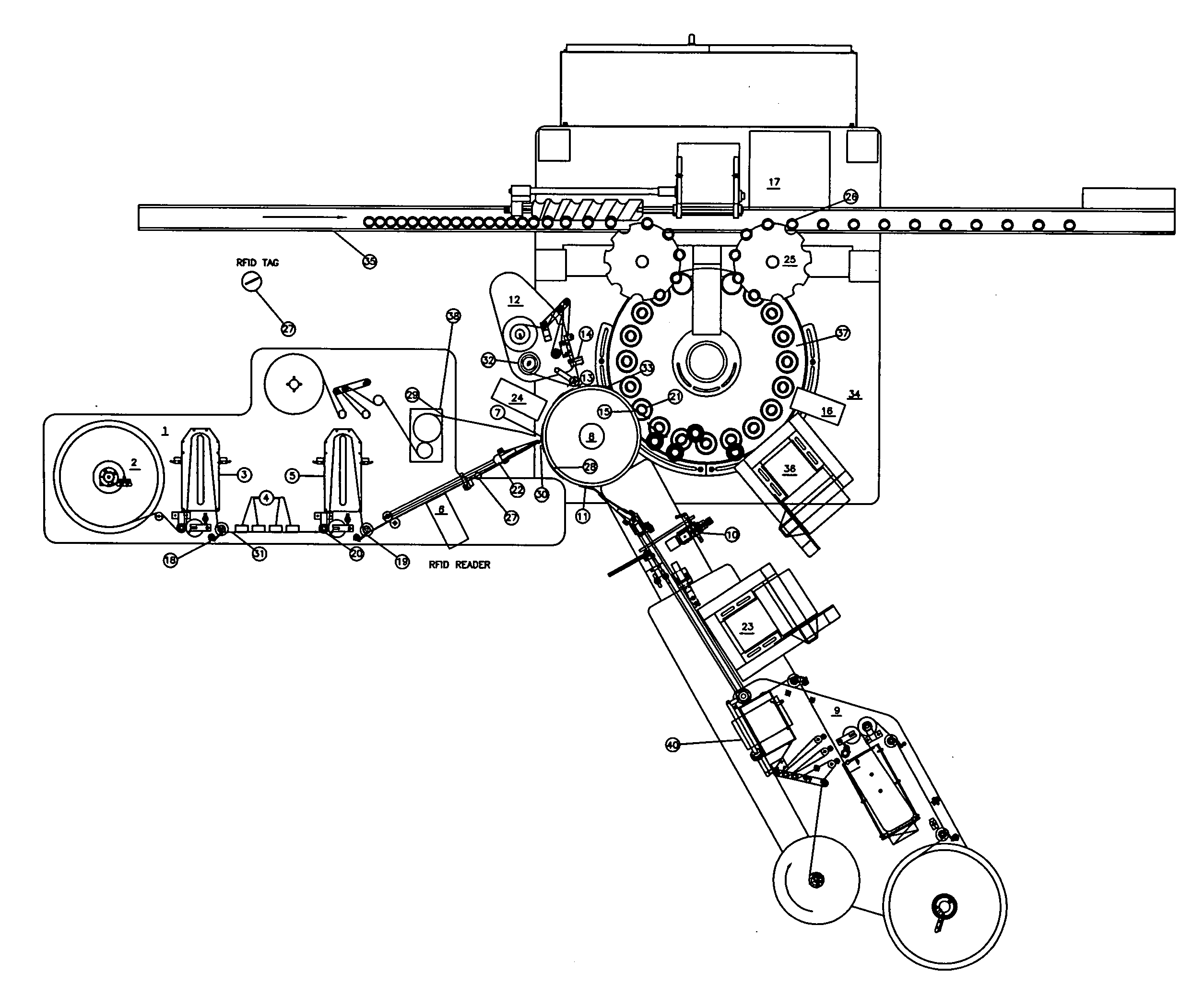
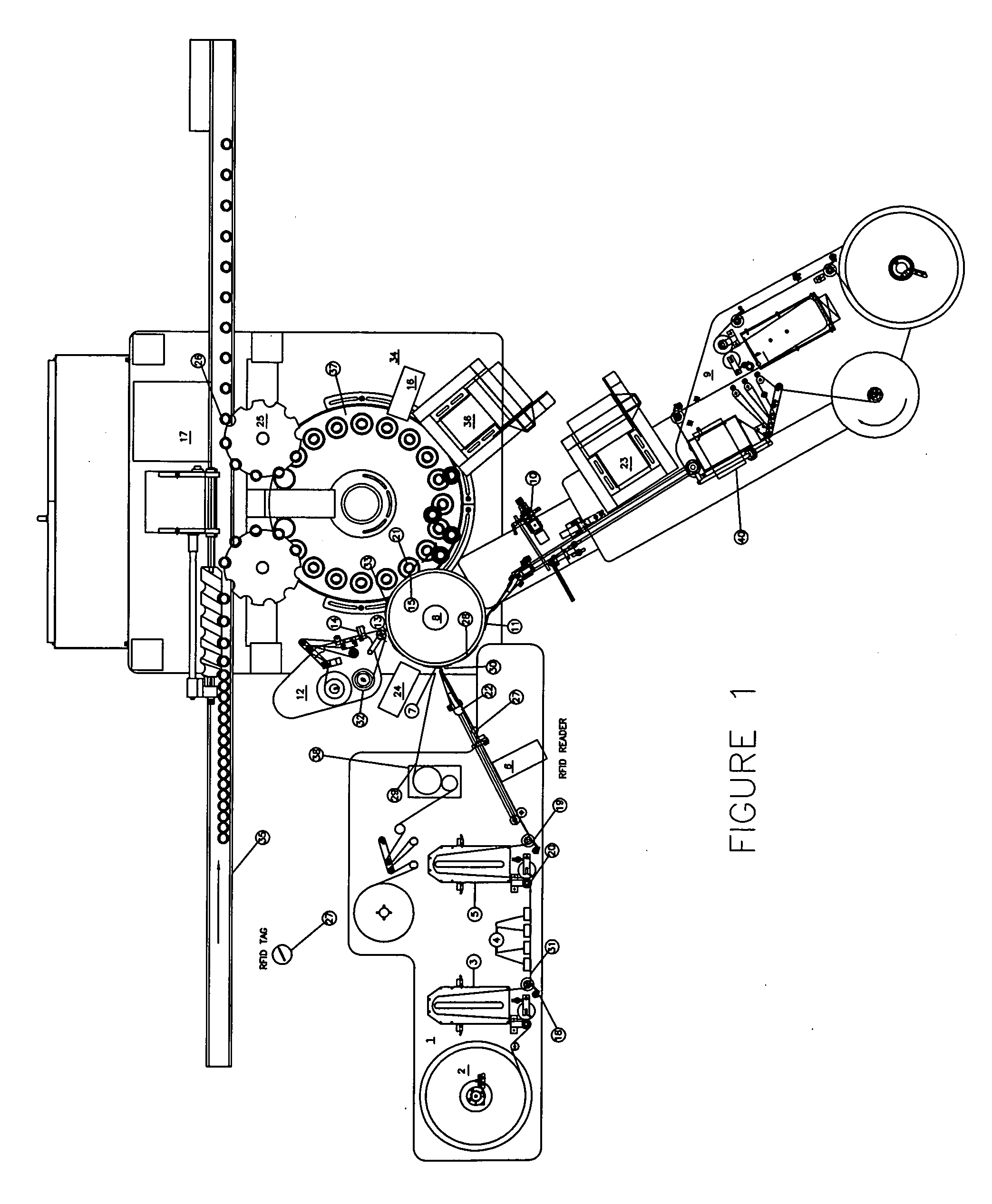
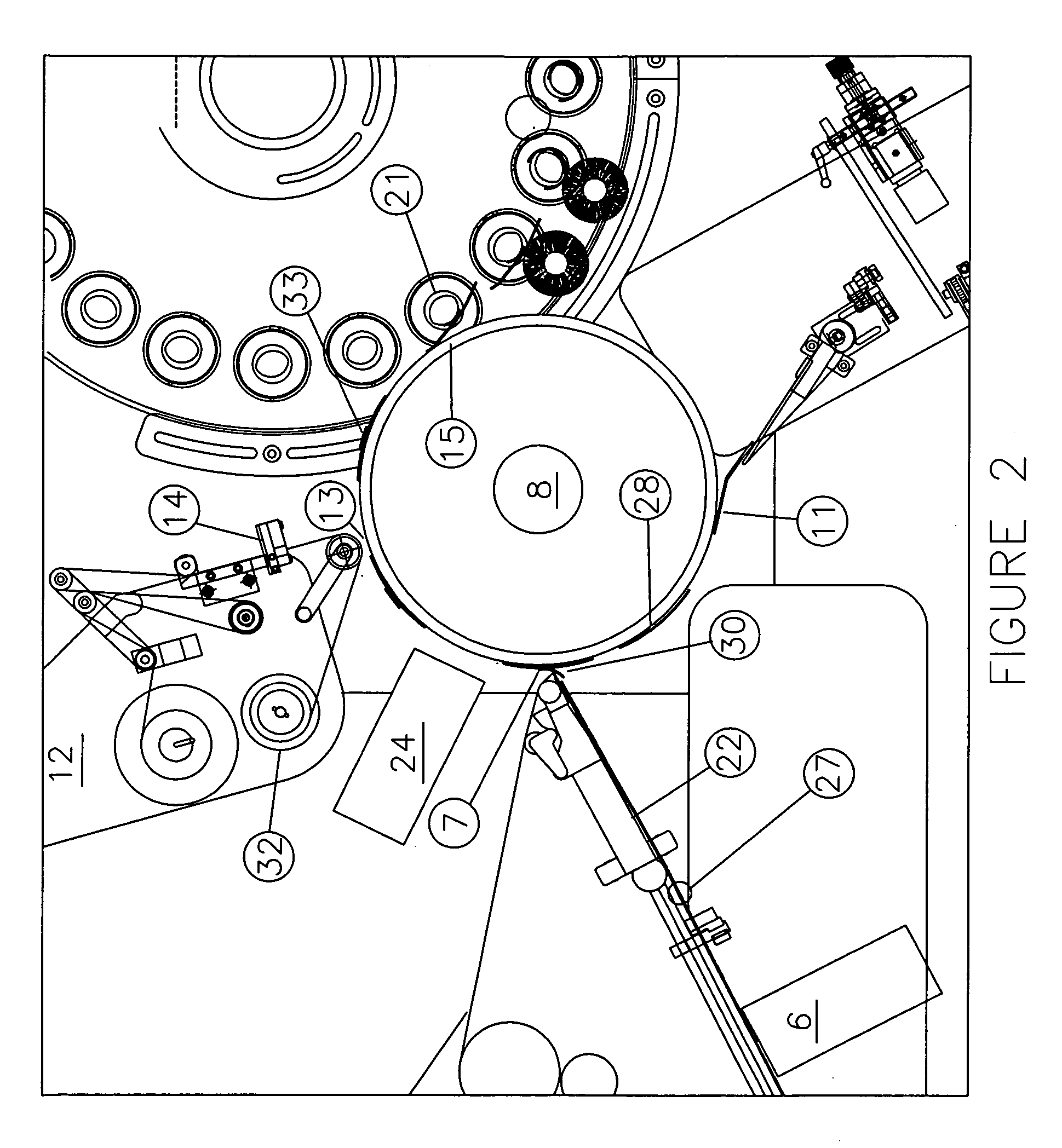
[0020]FIG. 1 is a general layout of the equipment used in the present invention. FIG. 2 is a blow-up of a portion of FIG. 1 for ease of reading.

Description of Numbered Components

[0021]1. RFID tag applicator[0022]2. 18″ Supply spool for tags[0023]3. Vacuum unwind loop box[0024]4. RFID writers[0025]5. Second Vacuum unwind loop box[0026]6. RFID tag antenna[0027]7. Tag application point[0028]8. Vacuum Drum[0029]9. Pressure Sensitive Label Head[0030]10. Vision Camera[0031]11. Pressure Sensitive Label Head application point[0032]12. Reconciliation unit[0033]13. Reconciliation unit label / tag pick off point[0034]14. Pick off verification sensor[0035]15. Label Application point[0036]16. RFID tag antenna[0037]17. Reject Blow off area with verification[0038]18. Hold back shoe[0039]19. Second hold back shoe[0040]20. Servo driven unwind roller[0041]21. Container at application point[0042]22. Interceptor—Retractable peel plate[0043]23. Laser or printer—Prints data matrix...


PUM

PropertyMeasurementUnit
Fractionaaaaaaaaaa
Speedaaaaaaaaaa

Abstract

An apparatus and method for the fully automated application of RFID tags which are applied to the adhesive side of a pressure sensitive label with 100% verification and inspection and where any rejection occurs prior to the application of the label to a container.

Description

CROSS-REFERENCE TO RELATED APPLICATIONS[0001]Not applicable.FEDERALLY SPONSORED RESEARCH AND DEVELOPMENT[0002]Not applicable.FIELD OF THE INVENTION[0003]Apparatus and method for automatic RFID labeling.BACKGROUND OF THE INVENTION[0004]Serialization, i.e., the assignment of serial identification numbers to individual product items, has become a necessity in the pharmaceutical, generic, biological, food and beverage industries as a result of label counterfeiting, diversion of products, and theft. Many pharmaceutical companies are turning to serialization of products with a 2-D data matrix code, i.e. a two-dimensional matrix bar code consisting of black and white square modules arranged in either a square or rectangular pattern. The information to be encoded can be text or raw data. Usual data size is from a few bytes up to 2 kilobytes. The length of the encoded data depends on the symbol dimension used. The food industry frequently uses a YottaMark code , i.e., an integrated system fo...

Claims


Application Information

Patent Timeline
IPC IPC(8): B32B37/00
CPCB65C9/188B65C2009/0003Y10T156/17B65C2009/404B65C2009/0081
Inventor BASGIL, THOMAS MICHAELPITUCH, THOMAS
Owner WEILER LABELING SYST L L C
Why Eureka
Try Eureka