Cell flow device and method that provides a sequential linear flow of pressure resistance

a cell flow and pressure resistance technology, applied in the field of cushioning and padding constructions, can solve the problems of lack of utility, device and method of cell flow technology, and inapplicability of new and unique technology, so as to improve physiology, support our anatomy, and improve comfor

Active Publication Date: 2015-07-30
FULCRUM PROD DEV
View PDF3 Cites 10 Cited by
  • Summary
  • Abstract
  • Description
  • Claims
  • Application Information

AI Technical Summary

Benefits of technology

[0015]There is a need for an improved cell flow technology. There is a need for a platform technology that has the attendant advantages with the utility, device and method of this given technology. Cell flow technology preserves the advantages of prior art and invention and it provides new advantages not found in the prior art. This technology of the present invention will also improve many current inferior utilities, devices and methods and it will overcome many disadvantages of such currently available art and invention. Foremost cell flow technology of the present invention will allow the creation of many new utilities, devices and methods, which are unattainable without its unique new and novel properties.
[0021]Cell flow technology utility, device and method of the present invention will greatly impact our daily living, improve comfort, support our anatomy, improve our physiology, and improve safety. As stated above this unique platform technology is able to reach a wide audience of products in our environment. It makes these products safer and improves their function.
[0022]Further cell flow technology of the present invention with its sequential linear flow of pressure resistance will allow for improved user comfort in pillows and cushioning products and improve operator safety in protective type products such as baseball batters helmets, baseball hats for pitchers, football and ice hockey helmets skateboarding, ski and water sports helmets, and youth soccer head protectors. This technology may greatly decrease stress and strain from heel strike in stride, stabilize and support mid stance and reduce strain on toe off. Further, making an operator less susceptible to common injuries associated with exercise, daily and work activities will improve lifetime endurance and health, most particularly in all the weight bearing joints of the body. It may limit motion and secure the head with a customized, variable and adjustable superior and unique fit and further help to prevent head injuries not limited to contusions and concussions in comparison to other technology presently available and last be made of perhaps the lightest of media such as helium, making the product more functional.
[0023]A final example of how such a platform technology may improve our lives and create a safer environment is in automotive vehicle roadside safety products such as roadway transition abutment safety barriers. This technology may be used to slow a motor vehicles velocity less abruptly upon impact and decrease vehicle damage and occupant trauma by absorption of the energy created in the impact.
[0024]This platform technology of the present invention may reduce the velocity of the vehicle slower than traditional abutment barrier's, presently in place,
[0025]Thus, it may absorb energy and lessen vehicle mass deformation lessening the damages of motor vehicles and lessening the injuries of motor vehicle occupants in a motor vehicle traffic accident. Multiple family cells that may further contain computerized and motorized continuance valves, which are properly and variably calibrated may accomplish this individually and collectively as a team. The multitude of continuance cells would slow the vehicle's velocity, slower than current traditional roadway transition abutment safety barriers, which more abruptly stop the motor vehicle causing great damage and injury.

Problems solved by technology

Currently this new and unique technology is not applied.
There have been a number of unsuccessful attempts in the prior art to address the aforementioned needs that such a method will solve.
It gives the consumer somewhat similar utility such as support and comfort however it lacks the utility, device and method of cell flow technology, which further illustrates the need for such a technology.
It's utility, device, and method does not to allow transfer of media, air, gas liquid, or other substrate or mixture thereof, by a sequential linear flow of pressure resistance from continuance cells of a family cell with different degrees of elastic potential energy always endogenously exerting different amounts of elastomeric abilities do to the different properties of the manufactured plastics that deliver different degrees of elastic deformation.
However, in reality since the two or more bladders have equal pressure, equal elastic deformation and equal finite volume it is not conceived that this utility, device and method would allow for a transfer of air between the bladders.
It is an air cushion to replace other cushioning material of which certainly would be heavier in a helmet and thus less functional and desirable.
However, none of the above patents have continuance cells from a family cell of two or more with different degrees of elastomeric capabilities.

Method used


Image

  • Cell flow device and method that provides a sequential linear flow of pressure resistance
  • Cell flow device and method that provides a sequential linear flow of pressure resistance
  • Cell flow device and method that provides a sequential linear flow of pressure resistance

Examples


first embodiment

[0031]In accordance with the present invention, a family cell of the present invention is illustrated in FIG. 1. Referring to FIG. 1, the family cell is depicted in 4. The secondary continuance cell 5 is in the format of an unequal size, or decreased volume capability. Further illustrated is a non-congruent shaped primary cell 6. The secondary cell 5 and the primary cell 6 of this family cell 4 in FIG. 1 are connected by conduits 2a and 2b with respective properly and variable calibrated valves 7a and 7b therein. The family cell with the use of an operator, motor, or any form of pressure resistance, sequentially transfers, air, gas liquid, or other substrate or mixture thereof, with the advantage of its properly calibrated and variable valves 7a and 7b by a sequential linear flow of pressure resistance, generally referenced as 8, from the fluidly connected primary continuance cell 6 to its familiar interactive and fluidly connected secondary continuance cell 5. The secondary cell 5 ...

embodiment 58

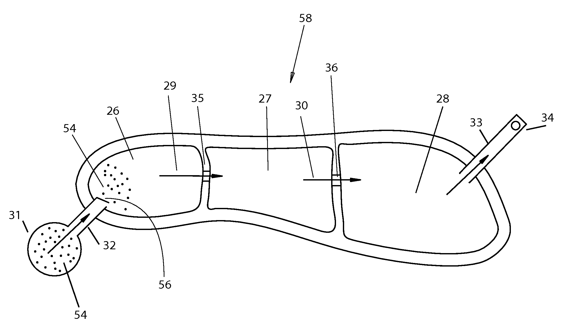
[0037]FIGS. 3A and 3B, show a further embodiment 58 of the present invention. FIG. 3A shows a top view of the embodiment while FIG. 3B shows a side view thereof. FIGS. 3A and 3B a number of continuance cells 26, 27, 28 with varying degrees of elastomeric potential 37, 38 and 39.

[0038]In FIGS. 3A, and 3B the continuance cells possess the same differences in elastic deformation capabilities as described above in FIG. 2. Furthermore the cause of said elastomeric abilities are the similar. In FIG. 3B there is a decrease elastomeric capability of the materials of the continuance cells from greatest in cell 26 to weakest in cell 28. In this embodiment the continuance cells have the added capability of operator force to further media from cell 26, to 27, and then to 28. More specifically the down force of heel strike of the operator on the continuance cell 26 in FIG. 3B will together with the feature of elastic potential energy inherent to the elastic deformation 37 of said cell 26 will fu...


PUM


Abstract

Cell flow device and method provides a sequential linear flow of pressure resistance includes a family cell of two or more continuance cells. These continuance cells have the same or different size and shape. They also have different degrees of elastomeric capability and are in fluid connection with the advantage of a properly calibrated valve(s) and will transfer air, gas, liquid, or other substance or media, or mixture thereof by a sequential linear flow of pressure resistance from a reservoir or external source through different degrees of elastic potential energy, geometric advantages, or introduction of a force. Thereby, the family cell performs the predetermined function in any device that uses the technology for a wide array of uses for users and operators thereof.

Description

CROSS REFERENCE TO RELATED APPLICATION[0001]This application is related to and claims priority from earlier filed Provisional Patent Application Ser. No. 61 / 932,738 filed Jan. 28, 2014, of which all contents thereof are incorporated herein by reference.BACKGROUND OF THE INVENTION[0002]The invention relates generally to cushioning, padding constructions and the component cells used therein for use in a wide array of devices such as cushion products, safety equipment, shoes and anatomical protective equipment. As part of providing a cushion or pad construction for these uses continuance cells are typically provided. They are filled with media such as gas, air, liquid or other substrate, or combination thereof to provide the needed method for whatever device the technology shall be employed.[0003]Clearly, there is a demand and a need for a new and novel platform technology that can provide an interminable sequential linear flow of pressure resistance. This is far superior to the device...

Claims


Application Information

Patent Timeline
Patent Type & Authority Applications(United States)
IPC IPC(8): A43B13/20
CPCA43B13/206A43B13/203A41D13/0155A43B13/189A43B17/026A43B17/035Y10T137/3584
Inventor ALMEIDA, ROBERT SCOTTSTERN, DOUGLAS EVAN
Owner FULCRUM PROD DEV
Why Eureka
Try Eureka