Scale structures and methods usable in an absolute position transducer

a transducer and scale structure technology, applied in transmission systems, instruments, code conversion, etc., can solve the problems of poor “information density”, large readheads, and large scales, and achieve the effects of high resolution, long scale lengths, and high resolution

Inactive Publication Date: 2005-03-15
MITUTOYO CORP
View PDF11 Cites 28 Cited by
  • Summary
  • Abstract
  • Description
  • Claims
  • Application Information

AI Technical Summary

Benefits of technology

This invention further provides optical absolute position encoders that obtain long scale lengths and high resolution by using an integrated scale track that includes a code portion that allows for long scale lengths and a periodic portion that allows for high-resolution determinations of the relative position between the

Problems solved by technology

Multiple track disadvantages include requiring overly-large-sized readheads, overly-wide scales and poor “information density” in at least some of the tracks.
Conversely, if multiple track configurations are made narrow, sensitivity to static and/or dynamic mounting misalignments and/or the need for more complicated readhead sensing or signal processing arises.
These disadvantages include limited absolute scale lengths if high resolution is desired, relatively low resolution if a long absolute scale length is desired, and/or the need for relatively more complicated readhead sensing or signal processing to achieve speeds, accuracies and resolution comparable to that achievable using a track of elements arranged periodically

Method used


Image

  • Scale structures and methods usable in an absolute position transducer
  • Scale structures and methods usable in an absolute position transducer
  • Scale structures and methods usable in an absolute position transducer

Examples


Embodiment Construction

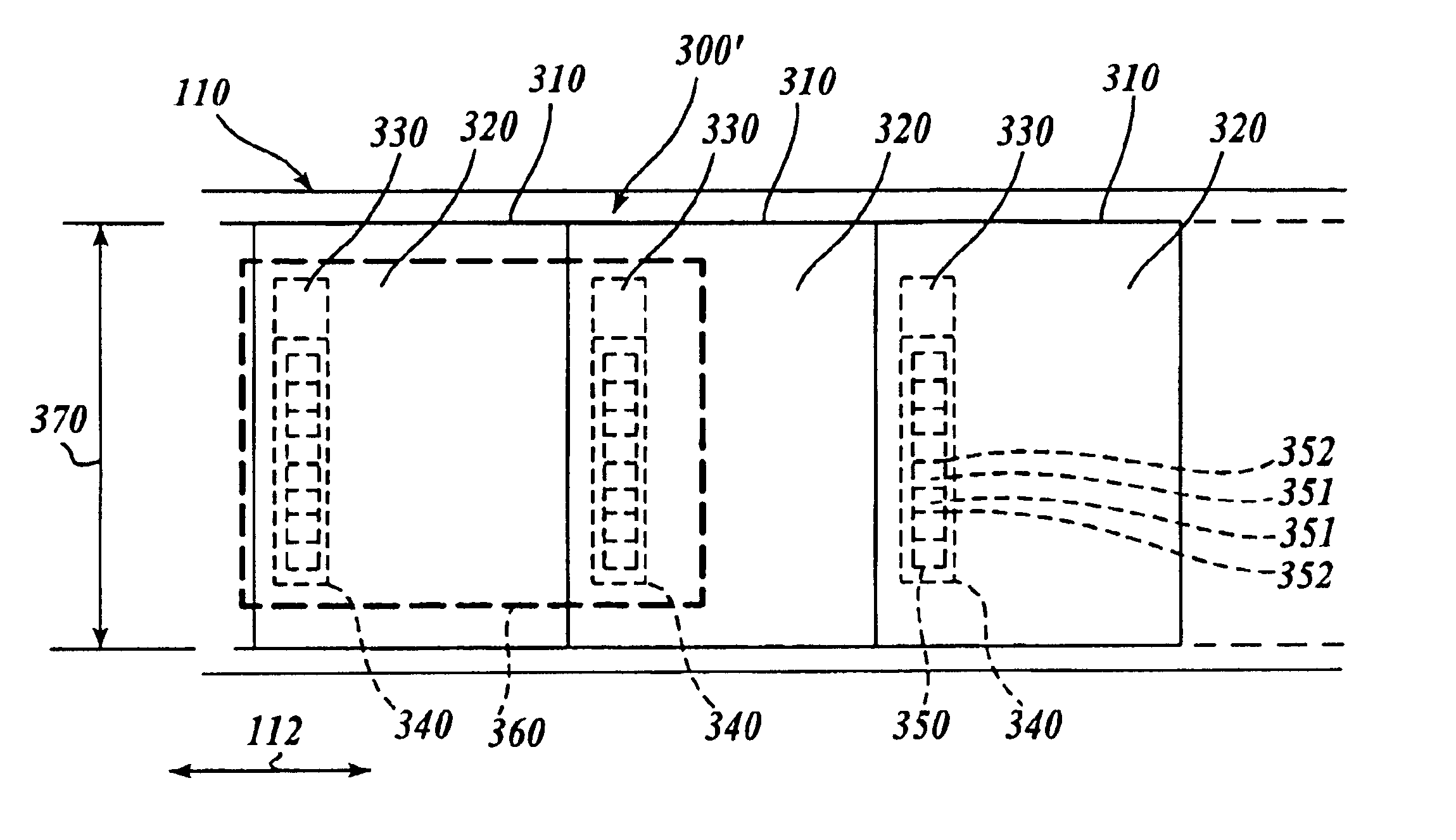
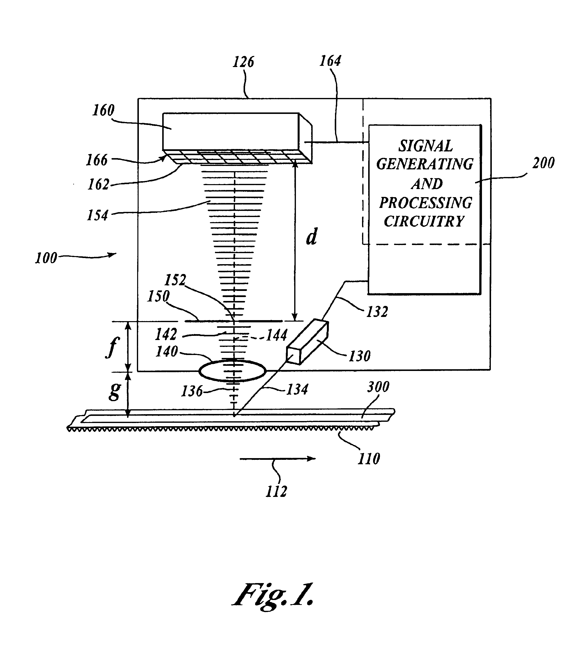
FIG. 1 is a block diagram of an optical absolute position encoder 100 usable with an integrated absolute scale according to this invention to generate an absolute position measurement. The optical absolute position encoder 100 shown in FIG. 1 includes a readhead 126, signal generating and processing circuitry 200 and a scale 110. The scale 110 includes an integrated scale track 300. In FIG. 1, the components of the readhead 126, and their relation to the scale 110 and the integrated scale track 300, are shown schematically in a layout that generally corresponds to an exemplary physical configuration, as further described below.

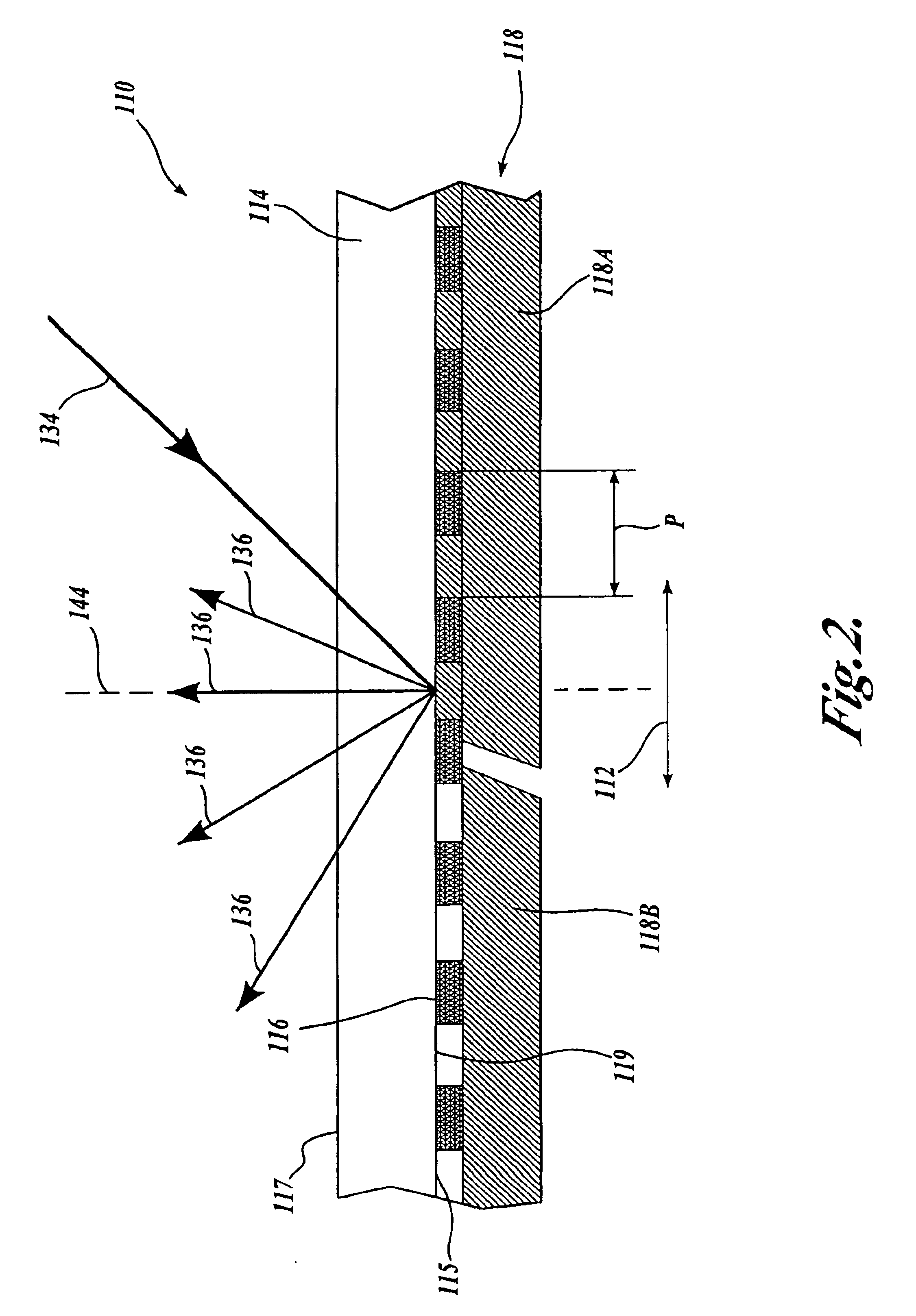
In particular, the scale 110 is positioned adjacent to an illuminating and receiving end of the readhead 126. When the scale 110 is illuminated by a light beam 134 emitted from that end of the readhead 126 by a light source 130, the emitted light beam 134 is selectively reflected back by the integrated scale track 300 on the scale 10 as a reflected light 136. ...


PUM


Abstract

An absolute position-sensing device is usable to measure the relative position of two elements. An absolute scale includes an integrated track extending along a measuring axis of the scale. The integrated track includes a plurality of code portions interleaved with, or embedded in, a plurality of periodic portions. Each periodic portion includes a plurality of periodically-placed incremental scale elements. Each code portion includes a plurality of code elements indicative of an absolute measurement value. The code elements are arranged in code element zones along the direction perpendicular to the motion axis, and are detectable by associated variations along the direction perpendicular to the motion axis. The offset of the periodically placed elements relative to a readhead of the device is combined with the absolute measurement value to determine an absolute position.

Description

FIELD OF THE INVENTIONThis invention relates to an absolute position optical displacement-sensing device.BACKGROUND OF THE INVENTIONAbsolute position encoders use a scale structure that allows the position of a readhead relative to a scale to be determined without requiring any reference to a given starting point along the scale. A variety of absolute position encoders are known which use multiple information tracks along the scale.In many conventional capacitive and inductive absolute position encoders, the scale structures include two or more tracks that have different periodic spatial wavelengths that, in combination, uniquely identify the position of the readhead relative to the scale within a limited distance. U.S. Pat. No. 5,886,519 discloses one embodiment of such an inductive absolute position encoder.The '519 patent also discloses an embodiment that includes a track having a periodic spatial layout of the sensible elements and a separate, code, track that includes a series ...

Claims


Application Information

Patent Timeline
IPC IPC(8): G01D5/245G01D5/12G01D5/26G01D5/347G01D5/30G01B21/02G01D5/249
CPCG01D5/2455G01D5/34792
Inventor PATZWALD, ANDREW M.ATHERTON, KIM W.
Owner MITUTOYO CORP
Why Eureka
Try Eureka