Rotor skew methods for permanent magnet motors

rotor skew technology, which is applied in the direction of dynamo-electric machines, magnetic circuit rotating parts, and magnetic circuit shapes/forms/construction, etc., can solve the problems of torque ripple, general undesirable torque ripple, and high maintenance costs of electric motors equipped with commutators and brushes. to achieve the effect of reducing the torque ripple of a permanent magnet motor

Inactive Publication Date: 2005-03-15
FORD GLOBAL TECH LLC
View PDF9 Cites 73 Cited by
  • Summary
  • Abstract
  • Description
  • Claims
  • Application Information

AI Technical Summary

Problems solved by technology

It is well known that electrical motors equipped with commutator and brushes are susceptible to higher maintenance costs.
However, one of the well-known problems of the PM motors is torque ripple.
Torque ripple is generally undesirable in many PM motors applications, particularly at low speeds.
The additional controls add to the complexity and cost.
Additionally, the exact skewing arrangement between the rotor and stator generally results in a higher complexity in design and a higher manufacturing cost.

Method used


Image

  • Rotor skew methods for permanent magnet motors
  • Rotor skew methods for permanent magnet motors
  • Rotor skew methods for permanent magnet motors

Examples


Embodiment Construction

While the invention is susceptible to various modifications and alternative forms, specific embodiments thereof are shown by way of example in the drawings and will be described herein in detail. It should be understood, however, that the drawings and detailed description thereto are not intended to limit the invention to the particular form disclosed, but on the contrary, the intention is to cover all modifications, equivalents and alternatives falling within the spirit and scope of the present invention as defined by the appended claims.

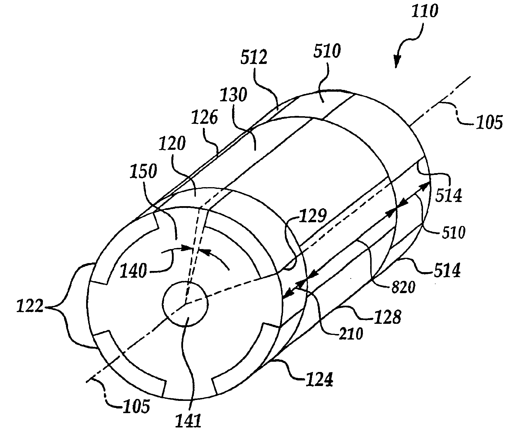
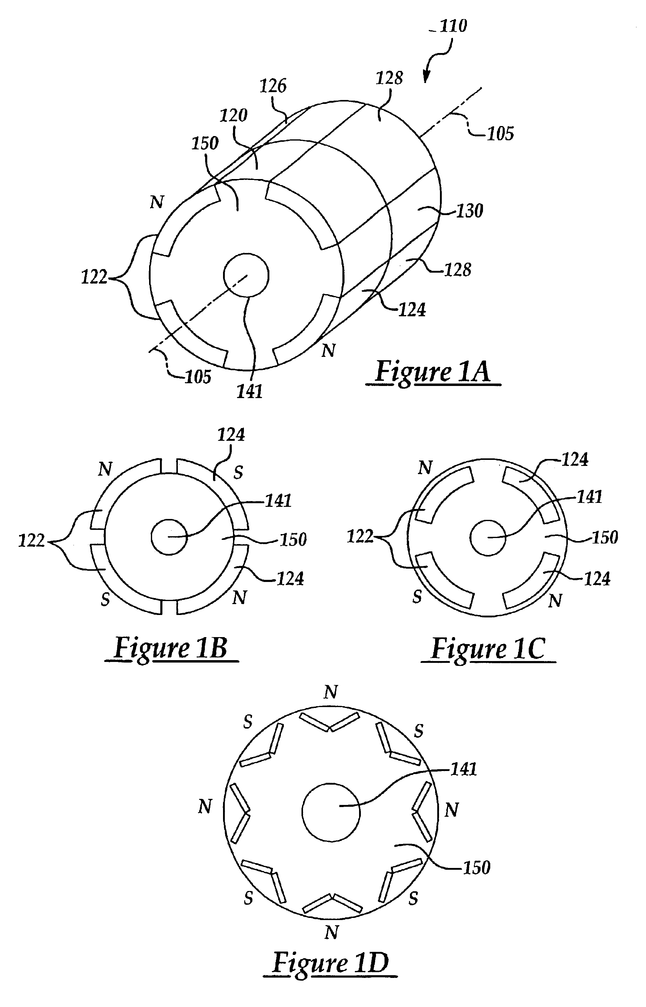
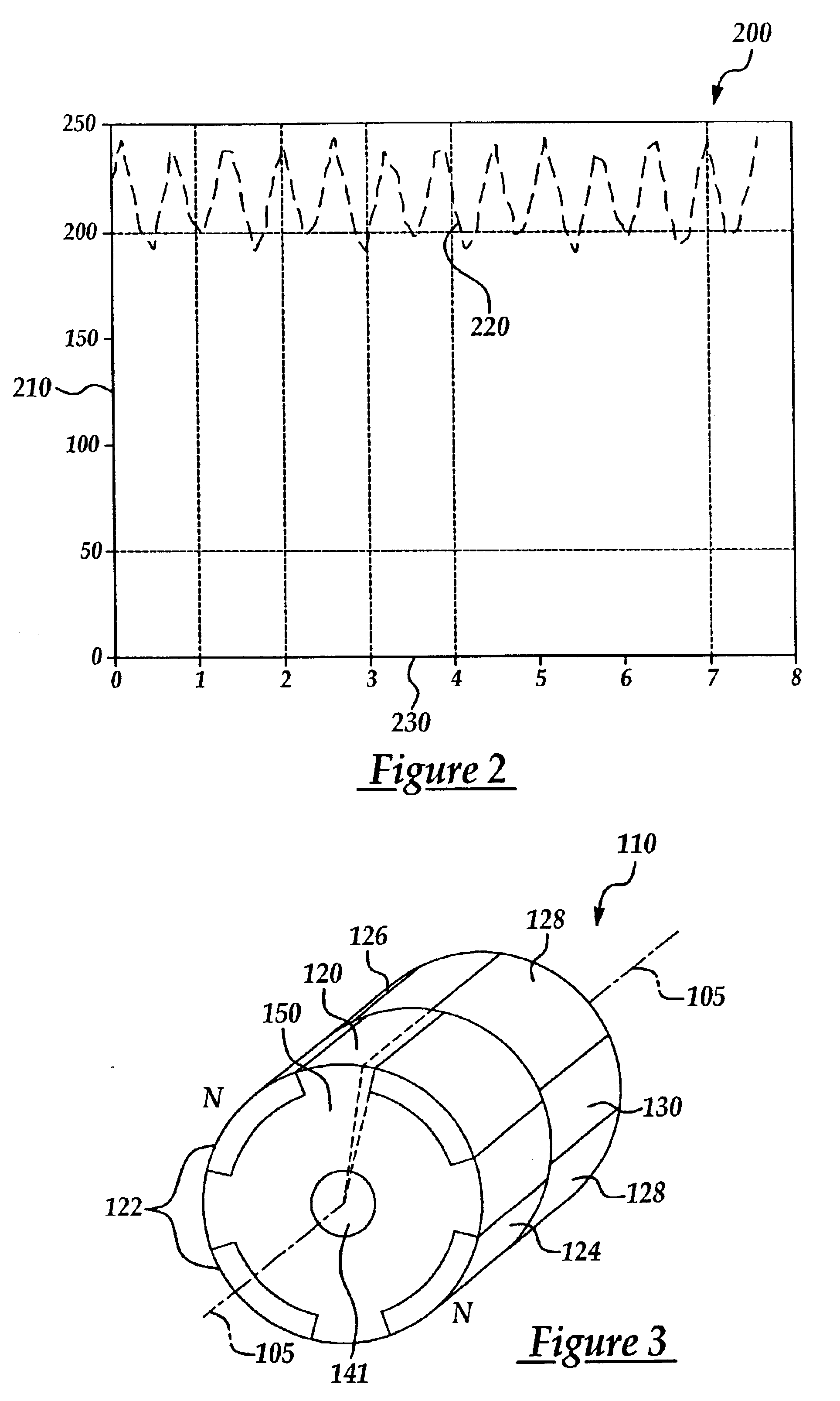
Elements, which appear in more than one figure herein, are numbered alike in the various figures. The present invention describes an apparatus and method to reduce torque ripple of a PM motor. According to one form of the invention, the PM motor includes a rotor having at least three segments. Each of the three segments are formed adjacent to another and aligned along an axis of the rotor. Each segment has at least one pair of permanent magnets dis...


PUM


Abstract

A permanent magnet motor to reduce torque ripple includes a rotor having at least three segments. Each of the three segments is formed sequentially adjacent and aligned along an axis of the rotor. Each segment has at least one pair of permanent magnets disposed at a substantially equal interval in a peripheral direction of the rotor. First and second segments are skewed relative to each other by a first angular displacement, and the first and third segments are skewed relative to each other by a second angular displacement. The first and second angular displacements are selected to cause a net sum of torque ripple produced by each of the segments to be substantially equal to zero during an operation of the motor.

Description

BACKGROUND OF THE INVENTION1. Field of the InventionThe present invention relates to an electric motor, and more particularly to a structure of a rotor assembly of a permanent magnet motor to improve the motor performance and reduce torque ripple.2. Description of the Relevant ArtThe motor is a well-known electrical machine that converts electrical energy into mechanical energy using magnetic field linkage. Permanent magnet (‘PM’) electric motors are known for their high efficiency. In recent years, especially since the introduction of rare-earth magnetic materials, PM motors have become popular since they eliminate the need for commutator and brushes, which are commonly used with conventional DC electric motors. The absence of the external rotor excitation eliminates losses on the rotor and makes PM motors more efficient. It is well known that electrical motors equipped with commutator and brushes are susceptible to higher maintenance costs. The brushless design of the PM motors al...

Claims


Application Information

Patent Timeline
Patent Type & Authority Patents(United States)
IPC IPC(8): H02K1/27
CPCH02K1/278H02K2201/06
Inventor LIANG, FENG
Owner FORD GLOBAL TECH LLC
Why Eureka
Try Eureka