
Square wave three-phase brushless permanent magnetic DC motor

A DC motor, three-phase technology, applied to synchronous motors with stationary armatures and rotating magnets, electric components, magnetic circuit rotating parts, etc., to achieve the effects of reduced copper consumption, low production costs, and stable torque

Active Publication Date: 2009-02-18
SCBD (ANHUI) E TECH CO LTD
View PDF0 Cites 61 Cited by
  • Summary
  • Abstract
  • Description
  • Claims
  • Application Information

AI Technical Summary

Problems solved by technology

[0006] The present invention will solve the problems existing in the existing square wave permanent magnet motor and sine wave permanent magnet motor, and propose a square wave permanent magnet motor with new principle, new structure, high performance and low cost

Method used

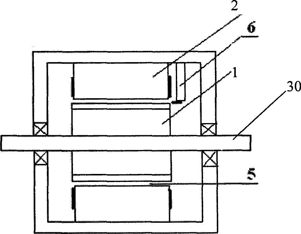

Image

  • Square wave three-phase brushless permanent magnetic DC motor
  • Square wave three-phase brushless permanent magnetic DC motor
  • Square wave three-phase brushless permanent magnetic DC motor

Examples


Embodiment Construction

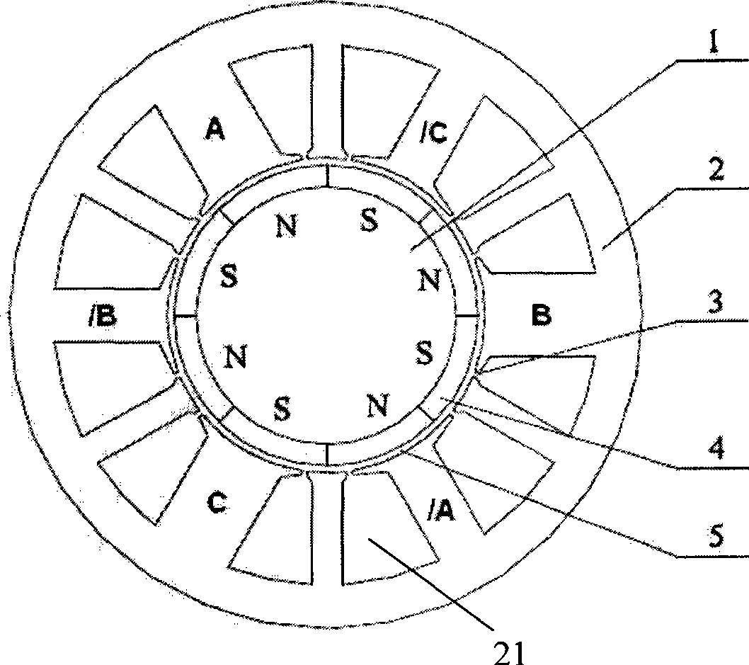
[0026] A preferred embodiment of the present invention is figure 1 with figure 2 shown. from figure 2 The general structure of this three-phase brushless permanent magnet DC motor can be seen in the figure. Its main components include rotor 1, stator 2, rotating shaft 30, etc. The physical air gap 5 between rotor 1 and stator 2 is 0.2-2mm. Among them, the Hall position sensor is used as the rotor position sensor. The magnetic sensitivity direction of the Hall position sensor is consistent with the normal direction of the rotor. ~3mm air gap.

[0027] from figure 1 It can be seen that the rotor core is equipped with multi-pole permanent magnets 4, and these permanent magnets generate an air gap magnetic field; figure 1 There are 4 pairs of 8 permanent magnets, and 8 magnetic poles N and S are arranged alternately, that is to say, the number of magnetic poles of the rotor is 2P=8. During specific implementation, the permanent magnet 4 may be a radially magnetized tile-sh...


PUM


Abstract

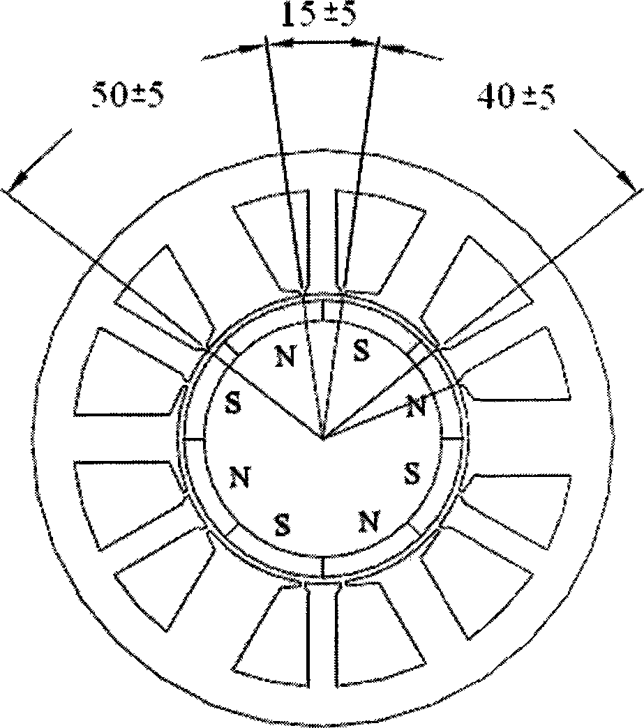
The invention relates to a square wave three phase brushless permanent magnet dc motor. In order to solve the problems existed in the prior square wave permanent magnet motor and sine wave permanent magnet motor, a magnetic pole number 2P is equal to 8 on a rotor iron core; a slot number Z is equal to 12 of a stator iron core, twelve teeth comprises three big teeth, three middle teeth and six small teeth;a mechanical angle ratio of the big teeth is 50 degree + / - 5 degree, the mechanical angle ratio of the middle teeth is 40 degree + / - 5 degree,the mechanical angle ratio of the small teeth is 15 degree + / - 5 degree,and a total mechanical angle ratio of one big tooth plus one middle tooth plus two small teeth is equal to 120 degree.The three phase concentrated windings respectively wind on the big teeth and middle teeth, each phase only has two concentrated windings and the three phase motor only has six concentrated windings. The motor can generate a stable torque when driven by a three phase square wave current and a torque fluctuation index is equivalent to that of the sine wave permanent magnet. The motor of the invention has a series of advantages of minimum winding end, minimum air gap, minimum material, minimum locating torque and minimum loss or the like.

Description

technical field [0001] The present invention relates to permanent magnet motors, and more particularly, to a square wave three-phase brushless permanent magnet direct current motor suitable for direct drive and position and velocity servo control applications. Background technique [0002] Permanent magnet motors can be divided into two categories: sine wave and square wave according to the driving current and back EMF waveform. A sine wave permanent magnet motor is generally called a permanent magnet synchronous motor (PMSM), or a sine wave AC servo motor. Another type of square-wave permanent magnet motor is called a square-wave brushless DC motor (BLDCM). [0003] During the 1980s, square wave permanent magnet motors were widely used. The external characteristics of square wave permanent magnet motors are basically the same as those of brushed DC motors, and the control is relatively simple, but its biggest disadvantage is that there are large principle commutation torqu...

Claims


Application Information

Patent Timeline
IPC IPC(8): H02K29/00H02K1/27H02K1/16H02K29/08
CPCH02K21/16H02K29/08H02K1/148
Inventor 李铁才漆亚梅周兆勇孔翔蓝维隆徐飞鹏
Owner SCBD (ANHUI) E TECH CO LTD
Learn More